All following information is sourced from DIS and should be considered official.
All reference operational parameters are derived from the average of numerous computer diagnostics I have performed on the M51. My tolerance ranges for these parameters are much stricter than the official ones and should be considered recommended, not mandatory. Remember, each specific situation and engine specimen is unique!
The following information is written by a professional for professionals. You will not find answers here to questions like "why does my engine idle rough?" For that, there are forums with armchair experts and advisors of the "I did this and mine is fine" caliber.
Fault Codes List and Explanations
Explanation:
For an unknown reason, information was stored in the fault memory. If no negative effects are detected in the system, the fault can be ignored.
Explanation:
The fault is stored when the fuel quantity actuator is outside the specified parameter. This can be due to a mechanical or electrical fault.
Consequences in case of fault:
intermittent:
— Jerking while driving.
constant:
— Engine stalling due to fuel shutoff (emergency shutdown);
— DDE warning lamp illuminated.
Possible causes:
— Wiring to the injection pump faulty;
— Fuel quantity actuator in the injection pump faulty;
— DDE control unit faulty.
Fault tracing:
Relevant ECU pins: 1 and 2.
Observe the fuel quantity actuator sensor reading at idle:
Actual value: **** mV
Specified value: 2700 +/- 200 mV
Open circuit: > 4500 mV
The value should change according to load when engine speed increases. Check the signal at the control unit: connect a universal adapter between the control unit and the injection pump wiring harness. Check for a 12V square wave signal, approx. 300 Hz at idle, using a multimeter or oscilloscope.
Explanation:
Fault is stored in case of a short circuit in the valve supply circuit or when the ECU cannot activate it.
Consequences in case of fault:
— DDE warning lamp illuminated;
— Emergency mode active;
— Engine shutdown via emergency shutoff not possible;
— If test result unsatisfactory — no consequences;
— If short to ground — engine operation impossible.
Possible causes:
— Short circuit on pin 3;
— Fuel shutoff valve leaking or faulty.
Fault tracing:
Relevant ECU pin: 3.
Perform emergency mode test — see Special Functions .
Consequences in case of fault:
— DDE warning lamp illuminated;
— Reduced base quantity: 21 mg/stroke (full load limitation);
— Rough engine operation in lower speed range;
— Injection timing control (not regulation) active;
— EGR system deactivated.
Possible causes:
— Wires, connectors faulty;
— Injection start sensor faulty.
This fault is also stored as a consequence of missing injection and after engine shutoff, e.g., due to:
— Fuel shortage;
— Electric fuel shutoff valve faulty;
— Fuel quantity actuator faulty;
— Fuel quantity actuator potentiometer faulty;
— Crankshaft speed sensor faulty;
— Injection start sensor faulty;
— Very low engine speed during coasting can also lead to fault memory entry; erase the fault!
Fault tracing:
Relevant ECU pins: 5 and 12.
Observe injection start sensor reading at idle:
Actual value: **** mV
Specified value: 3100 — 3500 mV
Open circuit: approx. 10000 mV
Check power supply to injection start sensor (according to "Electrical Circuit Checks").
Explanation:
Fault is stored if the injection timing control unit is faulty, or if injection timing deviation exceeds 2 degrees for >20 seconds. Fault will also be stored with blocked fuel supply or deviation of internal injection pump pressure.
Consequences in case of fault:
— DDE warning lamp illuminated;
— Injection timing control (not regulation) active;
— Emergency injection timing value possible;
— Increased black smoke emission;
— Reduced base quantity: 21 mg/stroke (full load limitation);
— Rough engine operation in lower speed range;
— EGR deactivated;
Possible causes:
— Wires, connector faulty;
— Basic setting for injection pump incorrect;
— Internal injection pump pressure out of specification;
— Fuel filter clogged or supply pressure too low;
— Injection timing control solenoid valve faulty;
— DDE control unit faulty.
Fault tracing:
Relevant ECU pins: 10 (MV0) and 18, 19 (B-).
Observe injection timing:
Actual value: **** ° crankshaft
Specified value: **** ° crankshaft
Maximum difference at constant speed: 2 ° crankshaft.
Checks: See repair manual and diagnostic manual.
Consequences in case of fault, if supply voltage < 8.5 V:
— Difficult starting;
— Jerking while driving, engine stalls or won't start (ELAB and fuel quantity actuator);
— System operates with emergency injection timing value.
Possible causes:
— Wires, connectors in power supply circuit faulty;
— V-belt tension insufficient;
— Battery discharged or faulty.
Fault tracing:
Relevant ECU pins: 18, 19 (B-) and 16, 17 (B+).
Observe supply voltage value:
Actual value: **** V
Specified value: > 8.5 V
Check voltage during starting, at idle, and with consumers switched on.
Explanation:
Fault is stored when an open circuit, short circuit, or implausible signal is identified in the cruise control stalk circuit.
Consequences in case of fault:
— Cruise control system inoperative.
Possible causes:
— Wires, connectors to pins 20/13 faulty;
— Cruise control switch cluster faulty or not installed;
— DDE control unit faulty.
Note:
If cruise control is not installed, this fault is system-related and stored constantly; in this case, it can be ignored. However, check if the cruise control switch cluster (steering column stalk) is installed.
Fault tracing:
Relevant ECU pins: 20 and 13 (ground).
Request cruise control switch cluster values in various positions:
Actual value: **** mV
Specified values depending on position:
— Neutral: 3400 — 3600 mV
— Forward: 800 — 900 mV
— Rearward: 2600 — 2700 mV
— Press (Set/Resume): 1600 — 1900 mV
— Up (On): 1600 — 1900 mV
— Down (Off): 4100 — 4300 mV
Warning:
If actual value is about 4980 mV, cruise control is not installed. In this case, the fault can be ignored.
Explanation:
Fault is stored when an open circuit, short circuit, or implausible signal is identified in the potentiometer circuit. Fault also possible with faults in the needle lift sensor.
Consequences in case of fault:
— DDE warning lamp illuminated;
— Jerking while driving, engine stalls or won't start (ELAB and fuel quantity actuator);
— Fault "[5] Injection start sensor" may also be stored in fault memory.
Possible causes:
— Wires, connectors to pins 14/21/39 faulty;
— Injection pump connector wet or damp;
— Injection pump faulty;
— DDE control unit faulty.
Fault tracing:
Observe fuel quantity actuator potentiometer readings at idle:
Actual value: **** mV
Specified value: 2700 +/- 200 mV
Open circuit: > 4500 mV
Value should change according to load when engine speed increases.
Perform the following conditions:
1) Switch off engine!
2) Switch ignition on!
3) Wait at least 30 seconds! (fuel quantity actuator reaches its stop).
Specified value under these conditions: U = 640 — 880 mV.
If specified value not reached, check fuel quantity actuator sensor:
1) Switch ignition off.
2) Remove front manifold bracket.
3) Disconnect wiring harness connector to injection pump.
4) Connect test plug 13 5 170 (for DDE 2.1 M51) to the wiring harness.
5) Switch ignition on.
6) Check status of fuel quantity actuator sensor.
Fuel quantity actuator sensor: **** mV
Specified value with test plug connected: U = 950 — 1150 mV.
If specified value NOT reached:
— Connector faulty or excessive contact resistance;
— Wiring harness faulty (from connector to DDE control unit);
— DDE control unit faulty.
Remedial actions:
— Repair or clean connector;
— Repair wiring harness;
— Replace DDE control unit;
If specified value reached:
— Connector faulty or excessive contact resistance;
— Section of wiring harness from connector to injection pump faulty;
— Or fuel quantity actuator sensor faulty.
Remedial actions:
— Repair or clean connector;
— Repair adjacent wiring harness section;
— Replace injection pump with fuel quantity actuator sensor.
Explanation:
Using the test plug, you can determine whether the fault lies before or after the connector (wiring harness to injection pump).
Location: In the injection pump.
Explanation:
Fault is stored when no signal or an implausible signal is received from the speed sensor at 1980 rpm for > 10 seconds.
Consequences in case of fault:
— System operates with equivalent value V = 20 km/h;
— Cruise control inoperative;
— Jerking during gear shifts (manual transmission only);
— Surge damper activated;
— Possible failure of speedometer and fuel consumption indicator.
Possible causes:
— Wires, connectors faulty;
— Instrument cluster faulty.
Fault tracing:
Relevant ECU pin: 29.
Observe speed signal:
Speed: **** km/h
Warning:
Only rotate raised wheels slowly.
During checks, also see diagnostic program for Instrument Cluster.
Explanation:
Fault is stored when conflicting signals are received from the brake light switch and the brake light test switch relative to each other for > 60 seconds.
Consequences in case of fault:
— Cruise control operation impossible;
— If no brake light signal received, engine speed limited to 1200 rpm for manual, 1450 rpm for automatic transmission.
Possible causes:
— Wires, connector to pins 26/31 faulty;
— Brake light switch faulty or adjustment incorrect.
Fault tracing:
Relevant ECU pins: 26 (BRL) and 31 (BRT).
Observe switch positions:
Brake light switch: ****
Brake light test switch: ****
Press brake pedal, both switches should close. Brake light switch actuation point is 3 mm from start of pedal travel.
Consequences in case of fault:
— System operates with equivalent value 60 °C;
— Slight limitation of injected fuel quantity at full load.
Possible causes:
— Wires, connector faulty;
— Fuel temperature sensor in injection pump faulty.
Fault tracing:
Relevant ECU pins: 35 and 13 (ground).
Observe fuel temperature:
Fuel temperature sensor: **** °C **** mV
Open circuit: approx. -40 °C
Short to ground: approx. 130 °C
If temperature implausible, check resistance according to diagnostic manual.
Note:
Short to positive may damage the sensor!
Explanation:
Fault is stored when DDE detects water in the fuel filter or a fault in the circuit.
Consequences in case of fault:
— None;
— Warning lamp does not illuminate.
Fault tracing:
Drain water from fuel filter, then erase fault and perform test start, and re-check for stored faults.
Possible causes if fault reappears:
— Wires, connectors faulty;
— Sensor faulty.
Explanation:
Fault is stored when the signal from the position sensor is outside the norm (above 4 V and below 0.1 V). Fault also stored when signals from potentiometer and pedal switch are implausible relative to each other.
Consequences in case of fault:
— System operates with equivalent value 0%;
— No response to accelerator pedal input;
— Driving possible only at constant speed of 1200 rpm for manual, 1450 rpm for automatic transmission.
Possible causes:
— Wires, connectors faulty;
— Accelerator pedal position sensor faulty or incorrectly installed.
Fault tracing:
Relevant ECU pins: 25, 33, 37 and 13 (ground).
Observe potentiometer and switch of accelerator pedal position sensor:
Accelerator pedal position potentiometer: **** % **** mV
Specified value at idle: 353 — 451 mV
Accelerator pedal position switch: ****
Specified value:
— Accelerator pedal at rest (open): not pressed
— Accelerator pedal pressed (closed): pressed
Consequences in case of fault:
— Increased starting time with cold engine.
Possible causes:
— Wires, connectors faulty;
— Glow plug relay fuse faulty;
— Glow plugs faulty;
— Glow plug relay not working;
— Output stages faulty (short on pin 8 to positive).
Fault tracing:
Relevant ECU pins: 8 (GZS), 11 (LA1) and 41 (DIA).
Check resistance and current draw of glow plugs.
For glow plug control check, see repair manual.
Relevant ECU pin: 45 (DWA / EWS II).
Current EWS program in DDE control unit:
EWS mode: ****
A
If DWA is installed, and EWS II is not installed (up to 12/1994, DDE control unit in EWS mode 1).
Consequences in case of fault:
— DWA blocks fuel injection (attempt to start with DWA armed);
— Fuel quantity actuator set to zero delivery;
— Engine starting impossible or engine stalls.
Possible causes:
— Fault stored when attempting to start engine with alarm system armed, i.e., signal level from DWA is high (U > 7 V).
B
If EWS II is installed (from 01/1995, DDE control unit in EWS mode 2).
Consequences in case of fault:
— Engine starting impossible or engine stalls.
Possible causes:
— ISN code in EWS control unit differs from DDE control unit (incorrect EWS control unit connected or error in data transmission/processing):
— DDE/EWS synchronization performed with error or not yet done;
— Wire from EWS control unit faulty if ISN code not received;
— Temporary EMV interference in case of sporadic ISN code disturbance;
— EEPROM faulty, replace DDE control unit if ISN checksum incorrect;
— EWS control unit faulty.
C
If DDE control unit is not coded (in EWS mode 0).
Consequences in case of fault:
— Engine starting impossible or engine stalls.
Possible causes:
— Coding incorrect or not yet performed.
Note:
Electronic Immobilizer EWS II:
From 01/1995 all vehicles equipped with EWS II.
EWS modes in DDE system:
Mode 0: Delivery state, engine operation impossible.
Mode 1: Immobilizer with constant signal active (up to 12/1994). With EWS II installed, engine operation impossible.
Mode 2: Immobilizer with coded signal active (from 01/1995). Engine operation only possible with EWS II control unit and corresponding ISN code.
Explanation:
Fault is stored when signal from sensor is absent or outside permissible range.
Relevant ECU pins: 47 and 13 (ground).
Consequences in case of fault:
— DDE warning lamp illuminated;
— Limited engine operation possible;
— Increased (approx. 2000 rpm) or unstable idle speed;
— If failure occurs below 1800 rpm, engine may stall;
— If failure occurs in overrun, engine stops;
— Tachometer inoperative;
— EGR and cruise control deactivated;
— System operates with emergency injection timing value;
— Equivalent speed value calculated from injection start sensor.
Possible causes:
— Wires, connectors faulty;
— Loose mounting or speed sensor faulty;
— Incorrect sensor gap;
— Reference pins on flywheel faulty.
Consequences in case of fault:
— System operates with equivalent value 60/125 °C;
— Slight power reduction at full load.
Possible causes:
— Wires, connectors faulty;
— Temperature sensor faulty.
Fault tracing:
Relevant ECU pins: 52 and 13 (ground).
Observe intake air temperature:
Intake air temperature sensor: **** °C **** mV
Open circuit: approx. -40 °C
Short to ground: approx. 180 °C
If temperature implausible:
— Check resistance according to diagnostic manual.
Consequences in case of fault:
— System operates with equivalent value:
For fuel quantity adjustment: -20 °C
For injection timing: 50 °C
For glow plug control time: 50 °C
For A/C: 130 °C
— Increased idle speed;
— Poor cold starting characteristics;
— EGR deactivated.
Possible causes:
— Wires, connectors faulty;
— Temperature sensor faulty.
Fault tracing:
Relevant ECU pins: 53 and 13 (ground).
Observe engine temperature:
Engine coolant temperature sensor: **** °C **** mV
Open circuit: approx. -40 °C
Short to ground: approx. 130 °C
If temperature implausible:
— Check resistance according to diagnostic manual.
Explanation:
Fault is stored when an open circuit, short circuit, or implausible signal (< 480 hPa > 2300 hPa) is identified in the circuit.
Consequences in case of fault:
— System operates with equivalent boost pressure value 504/1000 hPa, atmospheric pressure 850 hPa;
— Engine power noticeably reduced;
— Maximum engine speed reduced;
— Injected fuel quantity reduced.
Possible causes:
— Wires, connectors faulty;
— Leak in pressure sensor or hose;
— Pressure sensor faulty.
Fault tracing:
Relevant ECU pins 51, 54, 13 (ground).
Observe boost pressure:
Boost pressure sensor: **** hPa **** mV
The boost pressure sensor measures absolute pressure in the intake system, i.e., the sum of atmospheric pressure and boost pressure. At idle, the value corresponds to local atmospheric pressure. When engine speed increases, boost pressure increases, i.e., the value should noticeably rise; with vehicle stationary at 3000 rpm, by 150-300 hPa.
Note:
Equivalent atmospheric pressure value is only reset during the next idle phase.
Explanation:
Fault is stored when implausible data transmission within DDE is identified.
Consequences in case of fault:
— Processor 1 failure: Reduced power, reduced driving comfort, increased idle speed.
— Processor 2 failure: Reduced power, reduced driving comfort.
— Engine knocking;
— Black smoke emission while driving.
Possible causes:
— DDE control unit faulty.
Consequences in case of fault:
— Engine shuts off;
— Engine knocking;
— Black smoke emission while driving.
Possible causes:
— DDE control unit faulty.
Relevant ECU pins: 8 (GZS), 10 (MV0), 11 (LA1), 6 (AGR) and 9 (KOA).
Consequences in case of fault:
— Glow plug relay activation impossible, additionally fault 41 Glow Plug Control Time stored;
— Injection timing solenoid valve MV0, injection timing deviation from nominal, additionally fault 10 Injection Timing Adjustment / Solenoid Valve stored;
— DDE preheating warning lamp (LA1), no indication;
— A/C not activated;
— EGR switching valve activation, no EGR.
Possible causes:
— One or more output stages faulty.
Consequences in case of fault:
— Reduced base quantity to 21 mg/stroke (full load quantity limitation);
— Insufficient engine power.
Possible causes:
— Boost pressure sensor or turbocharger hoses faulty;
— Pressure control unit or wastegate faulty/sticking;
— Turbocharger faulty.
Note:
Fault stored if measured boost pressure at engine speed above 3000 rpm:
— Exceeds calculated value by more than 304 hPa;
— Is more than 510 hPa below calculated value.
Specified value:
Boost pressure at 3000-4000 rpm (highway driving, full load and braking regulation):
For 105 kW: 950 — 1150 hPa + atmospheric pressure;
For 85 kW: 750 — 900 hPa + atmospheric pressure.
Consequences in case of fault:
— Adjustment functions cannot be changed;
— Equivalent values active.
Possible causes:
— EEPROM cells defective.
Consequences in case of fault:
— Adjustment functions cannot be changed;
— Equivalent values active.
Possible causes:
— EEPROM cells defective.
Consequences in case of fault:
— Poor shift smoothness;
— Power reduction from approx. 1500 rpm.
Possible causes:
— Inside DDE control unit;
— Pins 40 and 43;
— Connection to EGS control unit.
Consequences in case of fault:
— Poor shift smoothness;
— Power reduction from approx. 1500 rpm.
Possible causes:
— Inside DDE control unit;
— Pins 40 and 43;
— Connection to ASC control unit.
Note:
For E36 series vehicles with manual transmission without ASC (3Y3), the fault can be ignored.
Live Data and Reference Parameters
47 Engine Speed:
Manual transmission:
— Specified: 750 rpm (± 50)
— Actual: 750 rpm (± 50)
Automatic transmission:
— Specified: 800 rpm (± 50)
— Actual: 800 rpm (± 50)
21 Fuel Quantity Actuator Potentiometer: 2600 mV (± 50 mV)
— Actual value.
59 Idle Speed Correction: **** rpm
— Specified value.
58 Injected Fuel Quantity: 5.5 mg/stroke (± 0.5 mg)
— Specified value.
37 Accelerator Pedal Position Potentiometer: 0% | 353 - 451 mV
— Actual value.
25 Accelerator Pedal Position Switch - Idle Switch: ****
— Actual value.
53 Engine Coolant Temperature Sensor: 88 - 92 °C | 1295 - 1135 mV
— Actual value.
52 Intake Air Temperature Sensor: **** °C | **** mV (depending on ambient temperature)
— Actual value.
35 Fuel Temperature Sensor: 20 - 60 °C | **** mV
— Actual value.
20 Cruise Control Switch Cluster: 3400 - 3600 mV
— Actual value.
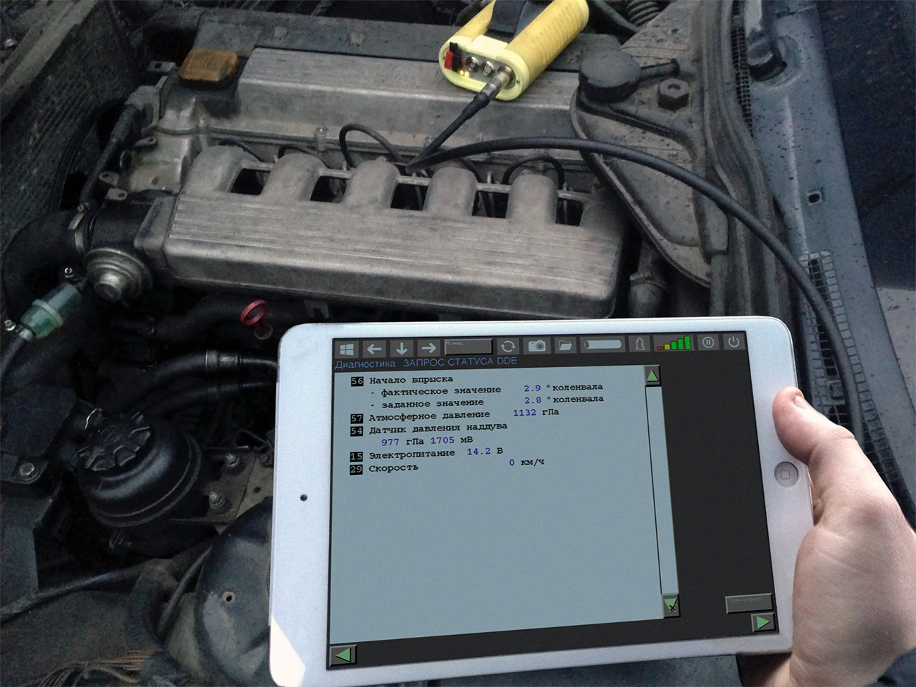
56 Injection Timing:
— Actual value: 2.8 ° crankshaft (± 1°)
— Specified value: 2.8 ° crankshaft (± 1°)
57 Atmospheric Pressure: 1007 hPa (depending on current atmospheric pressure)
— Actual value.
54 Boost Pressure Sensor: 1007 hPa | 1764 mV (at idle = atmospheric, at 3000 rpm = atmospheric + 150 - 300 hPa).
— Actual value.
15 Electrical Supply: 14.2 V (± 0.5 V)
— Actual value.
29 Speed: **** km/h
— Actual value.
3 Electric Fuel Shutoff Valve (ELAB): ****
— Specified value.
4 DDE Malfunction Indicator Lamp: ****
— Specified value.
11 Preheating Indicator Lamp: ****
— Specified value.
8 Glow Plug Relay Activation: ****
— Specified value.
45 Alarm System Status: ****
— Actual value.
26 Brake Light Switch: ****
— Actual value.
31 Brake Light Test Switch: ****
— Actual value.
28 Clutch Switch or P/N Switch: ****
— Actual value.
44 A/C Switch: ****
— Actual value.
24 A/C Compressor Request from IHK Control Unit
— Actual value.
9 A/C Compressor Activation Signal from DDE Control Unit
— Specified value
Activation of Components/Actuators
6 Glow Plug Timing Relay
— Activated for 40 seconds with 1-second cycle. Check audibly.
8 EGR Switching Valve
— Activated for 40 seconds with 1-second cycle. Check signal by measurement.
9 A/C Compressor Clutch
— Activated for 40 seconds with 1-second cycle. Check response.
10 Injection Timing Control Solenoid Valve
— Activated for 40 seconds with 1-second cycle. Check response.
11 Preheating Indicator Lamp
— Activated for 40 seconds with 1-second cycle. Check response. For control units with manufacturing date < 167, activation is only for 2 seconds.
Special Functions
1 Emergency Mode Test. This test checks the emergency shutdown of the injection pump.
Engine speed: **** rpm
— Start engine! Immediately after, begin emergency mode test with key.
— Test in progress! Wait!
— Emergency mode test completed!
YES:
External emergency circuit OK.
NO:
Is engine speed increase possible only up to approx. 1500 rpm?
Yes:
Emergency shutdown circuit OK (minor leakage losses do not stop engine).
No:
Possible causes if emergency mode test result unsatisfactory:
— Electric fuel shutoff valve faulty;
— Leakage in shutoff valve, possibly due to clogging;
— DDE control unit faulty.
Note:
To ensure reliable engine shutdown, the DDE control unit activates the electric fuel shutoff valve (ELAB) continuously under certain circumstances. In this case, cancellation of this activation is only possible via ignition OFF/ON.
2 Correction Functions
Deviation from neutral position:
— New specified value: **** rpm
— Current value: **** rpm
Set desired specified value with INCREASE or DECREASE keys. Then send to ECU with key.
Idle speed adjustment range:
— Up to +91 rpm (4 steps);
— Up to -91 rpm (4 steps).
Deviation from neutral position:
— New specified value: step ****
— Current value: step ****
Step 0 — neutral position.
+ — increase fuel quantity.
- — decrease fuel quantity.
Set desired specified value INCREASE or DECREASE . Then send to ECU with key.
Starting fuel quantity adjustment range:
— Up to level +31 (+4.8 mg/stroke)
— Up to level +59 (+5.0 mg/stroke)
— Up to level -37 (-5.0 mg/stroke)
— Up to level -59 (-5.0 mg/stroke)
Note:
Correction of starting fuel quantity allows minor adjustments to the fuel quantity calculated by the DDE control unit.
Correction should ONLY be performed after thorough checking of the fuel injection system.
Measure current value at about 10 steps, then perform test start.
Scope:
During engine start phase until idle speed is established.
Choose a lower step if:
— Heavy black smoke emission during and immediately after starting process.
Choose a higher step if:
— Long cranking (longer than 3 seconds at air temperature above 5 °C), even if no heavy black smoke after start.
Deviation from neutral position:
— New specified value: step ****
— Current value: step ****
Step 0 — neutral position.
+ — increase fuel quantity.
- — decrease fuel quantity.
Set desired specified value with INCREASE or DECREASE . Then send to ECU with key.
Base quantity adjustment range:
— Up to level +16 (+2.0 mg/stroke)
— Up to level -37 (-5.0 mg/stroke)
Note:
Quantity correction allows small adjustments to injected fuel quantity, e.g., for lack of dynamic response with engine at operating temperature.
Correction should ONLY be performed after thorough checking of the fuel injection system for absence of systematic faults.
A consequence of increasing injected fuel quantity may be excessive smoking (test drive required for evaluation!).
Change current value by about 5 steps, then perform test drive to assess change in smoke level.
Scope:
— From starting speed to maximum engine speed.
To check effect at idle (engine at operating temperature), measure fuel consumption at idle.
Increasing fuel quantity manifests as reduced idle fuel consumption.
Choose a lower step if:
— Heavy black smoke emission under full load, even if no fault can be found in engine or DDE control unit.
Choose a higher step if:
— Insufficient engine power and not very heavy black smoke during driving.
Deviation from neutral position:
— New specified value: step ****
— Current value: step ****
Step 0 — neutral position.
+ — increase fuel quantity.
- — decrease fuel quantity.
Set desired specified value with INCREASE or DECREASE . Then send to ECU with key.
Full load fuel quantity limitation adjustment range:
— Up to level +3 (+2.3 %);
— Up to level -16 (-12.5 %).
Note:
Quantity correction allows small adjustments to injected fuel quantity, e.g., for lack of dynamic response with engine at operating temperature.
Correction should ONLY be performed after thorough checking of the fuel injection system.
Change current level by no more than 2 steps, then perform test drive.
Scope:
Only under full load, from idle speed upward.
Choose a lower step if:
— Heavy black smoke emission under full load, even if no fault can be found in engine or DDE control unit.
Choose a higher level if:
— Poor behavior when starting off and not heavy black smoke during driving.
Deviation from neutral position:
— New specified value: step ****
— Current value: step ****
Step 0 — neutral position.
+ — lower switching threshold (more EGR)
- — raise switching threshold
Set desired specified value with INCREASE or DECREASE . Then send to ECU with key.
EGR adjustment range:
— Up to level +103 (+3.8 mg/stroke)
— Up to level -122 (-4.4 mg/stroke)
Note:
Perform only upon request of BMW Service!
EGR correction allows minor adjustment of the EGR switching threshold.
When installing the following DDE control units, adjust:
— 5E5 on E34 525tds sedan with manual: level -60;
— 5M5 on E34 525tds sedan with manual: level -60;
— 5A4 on E34 525td sedan with manual: level -85;
— 5G3 on E34 525tds sedan and touring with automatic: level -60;
— 5F3 on E34 525td sedan and touring with automatic: level -60.
Deviation from U specified:
— Specified value: **** mV
— Current instrument reading: **** mV
U specified equals 0 mV - neutral position:
+ — increase fuel quantity;
- — decrease fuel quantity.
Set desired specified value with INCREASE or DECREASE . Then send to ECU with key.
Summing fuel quantity correction adjustment range:
— Up to +70 mV (7 steps);
— Up to -100 mV (10 steps).
Note:
Summing fuel quantity correction provides increase or decrease to the injected fuel quantity values stored in the characteristic map. This is achieved by raising or lowering the fuel quantity actuator voltage (U specified) and compensates for, e.g., lack of dynamic response when starting off under high load and/or at high ambient temperature.
Correction should ONLY be performed after thorough checking of the fuel injection system.
Change current level by about 20 mV, then perform test drive.
Scope:
Throughout entire load range, from idle to full load.
To check at idle (engine at operating temperature), measure fuel consumption at idle. Increasing fuel quantity manifests as reduced idle fuel consumption.
Choose decreased U specified if:
— Heavy black smoke emission under full load, if fault in engine or DDE control unit cannot be found.
Choose increased U specified if:
— Lack of dynamic response and not very heavy black smoke.
Activated injection timing characteristic map:
— Specified value: ****
— Current value: ****
Set desired specified value with INCREASE or DECREASE . Then send to ECU with key.
Injection timing characteristic map adjustment range:
0 — Injection timing map with EGR (basic setting);
1 — Injection timing map without EGR;
2 — Injection timing map with EGR.
Note:
Perform only upon request of BMW Service!
This correction allows adjustment of the injection timing characteristic map.
Note on DDE coding (with/without EGR):
When installing DDE control units of the following versions, there is no difference in the injection timing map between "with EGR" and "without EGR":
— From 5G1 (525 tds sedan/touring);
— From 5F1 (525 tds sedan/touring);
— From 3G1 (325 tds sedan/touring);
— From 3F1 (325 tds sedan);
— From 3N1 (325 tds sedan with ASC).
EC version 2 (from 01/1996):
— 3X1, 3X2 (325 tds sedan/touring without ASC, manual and automatic);
— From 3X3 (325 tds sedan/touring without ASC, automatic only);
— 3Y1, 3Y2 (325 tds sedan/touring with ASC, manual only);
— From 3Y3 (325 tds sedan/touring with/without ASC, manual only);
— 3V1, 3V2 (325 td sedan/touring without ASC, manual and automatic);
— From 3V3 (325 td sedan without ASC, automatic only);
— 3W1, 3W2 (325 td sedan with ASC, manual only);
— From 3W3 (325 td sedan with/without ASC, manual only).
Activated EGR characteristic map:
— Specified value: ****
— Current instrument reading: ****
Set desired specified value with INCREASE or DECREASE . Then send to ECU with key.
EGR characteristic map adjustment range:
0 — EGR map 0 (basic setting);
1 — EGR map 1;
2 — EGR map 2.
Note:
Perform only upon request of BMW Service!
This correction allows adjustment of the EGR characteristic map.
3 Replacing the DDE Control Unit
It is essential to determine precisely that the existing fault is indeed due to a faulty DDE 2 control unit! Replacing parts not causing the complaint leads to unnecessary warranty costs and may cause customer dissatisfaction.
Therefore first:
— Rectify all stored faults (also check in EGS and ASC control units);
— Clear fault memory, check that fault is not stored again (e.g., test drive).
Only if fault tracing does not lead to its rectification, and the fault message is stored again in the fault memory, follow the instructions below.
Note:
Read through completely first, then use MoDiC!
Procedure:
— Print check code;
— Perform control unit replacement procedure in "Programming" (MoDiC only!);
— Replace DDE 2 control unit according to Repair Manual;
— Rectify remaining faults in "Diagnosis" mode;
— After clearing fault memory, check if fault or malfunction is now eliminated, e.g., test drive or test start.
Note on correction functions in new DDE 2 control unit:
— If version numbers are identical - all correction values and maps are transferred;
— If new version number - EGR correction, characteristic maps are automatically coded with corresponding new values, remaining correction values adopted.
Instruction:
For this reason, check correctness of transferred correction values and maps (especially black smoke emission or similar), e.g., via test drive or engine run-in.
4 Replacing the Distributor Injection Pump
It must be confirmed that the cause of the existing fault is indeed a defective distributor injection pump! Replacing parts not causing the complaint leads to unnecessary warranty costs and may cause customer dissatisfaction.
Therefore first:
— Rectify all stored faults (also check in EGS and ASC control units);
— Clear fault memory, check that fault is not stored again (e.g., test drive).
Only if fault tracing does not lead to its rectification, and the fault message is stored again in the fault memory, follow the instructions below.
Note:
Read through completely first, then use MoDiC!
Procedure:
— Print check code;
— Switch ignition off, replace distributor injection pump according to Repair Manual;
— Then switch ignition on;
— Select "Diagnosis";
— All correction values and maps are retained, i.e., check correctness (especially black smoke emission or similar), e.g., via test drive or test start;
— Rectify remaining faults;
— After clearing fault memory, check if fault or malfunction is now eliminated, e.g., via test drive or test start.
ECU Connector Pin Assignment and Description
Markings:
A — Output
E — Input
M — Ground
Location:
Fuel quantity actuator in distributor injection pump.
Function:
The fuel quantity actuator is the actuator for the control sleeve.
Signal form:
Square wave signal.
Instrument reading:
Fuel quantity actuator sensor **** mV
See also Status request with specified values and explanations.
Measurement instructions:
— Oscilloscope;
— Frequency measurement;
— Fault memory.
Location:
Electric fuel shutoff valve in injection pump.
Function:
Electric shutoff valve to stop fuel supply.
Signal form:
With ignition on or engine running, the fuel shutoff valve is activated constantly, signal > 10 V. To stop fuel supply, ELAB is deactivated.
Measurement instructions:
— Multimeter;
— Fault memory.
Location:
DDE malfunction indicator lamp in instrument cluster.
Function:
Illuminates for severe fault in injection system.
Signal form:
If faults 1, 3, 5, 21 or 47 are stored and currently present, the DDE control unit supplies ground to pin 4 (DDE malfunction lamp illuminates).
Measurement instructions:
— Multimeter;
— Fault memory.
Location:
Injection start sensor in duration of injection injector (SD injector) cylinder 4.
Function:
Needle lift sensor for determining start of injector opening.
Signal form:
Sinusoidal signal.
Instrument reading:
Injection start:
— Actual value: **** ° crankshaft
— Specified value: **** ° crankshaft
Measurement instructions:
— Status request;
— Fault memory.
Location:
Glow plug relay.
Function:
Glow plug relay acts as switch for 6 glow plugs.
Signal form:
Ground during glow phase.
Measurement instructions:
— Multimeter;
— Fault memory;
— For glow plug control check, use Repair Manual.
7 — Reserved
Location:
EGR switching solenoid valve.
Function:
Returns exhaust gas to intake tract via vacuum-operated EGR valve.
Signal form:
Ground when EGR activated.
Measurement instructions:
— Multimeter;
— Fault memory.
Location:
A/C compressor relay.
Function:
Switch for A/C compressor relay.
Signal form:
Ground when A/C compressor relay activated (only with engine running).
Measurement instructions:
— Multimeter;
— Fault memory.
Location:
Injection timing control solenoid valve in distributor injection pump.
Function:
Injection timing adjustment.
Signal form:
Frequency.
Instrument reading:
Injection start:
— Actual value: **** ° crankshaft
— Specified value: **** ° crankshaft
Measurement instructions:
— Status request;
— Fault memory;
— Component activation;
— Frequency measurement.
Location:
Preheating indicator lamp in instrument cluster.
Function:
Illuminates during preheating phase.
Signal form:
Ground during preheating phase.
Measurement instructions:
— Multimeter.
Location:
Ground supply for injection start sensor in duration of injection injector (SD injector) cylinder 4.
Function:
Needle lift sensor for determining opening duration.
Signal form:
Sinusoidal form.
Instrument reading:
Injection start:
— Actual value: **** ° crankshaft
— Specified value: **** ° crankshaft
Measurement instructions:
— Status request;
— Fault memory;
— Component activation;
— Frequency measurement.
Location:
Shielding for injection start sensor and speed sensor.
Function:
Ground to fuel temperature sensor, charge air temperature sensor, speed sensor, boost pressure sensor, and cruise control switch cluster.
Signal form:
Ground.
Measurement instructions:
— Multimeter.
Location:
Shielding for control sleeve sensor and accelerator pedal position sensor.
Function:
Ground for control sleeve sensor and accelerator pedal position sensor.
Signal form:
Ground.
Measurement instructions:
— Multimeter.
Location:
DDE system relay.
Signal form:
Battery voltage U > 12 V.
Instrument reading:
Electrical supply: **** V
Measurement instructions:
— Multimeter;
— Fault memory.
Location:
DDE system relay.
Signal form:
Battery voltage U > 12 V.
Instrument reading:
Electrical supply: **** V
Measurement instructions:
— Multimeter;
— Fault memory.
Location:
DDE system relay.
Signal form:
Battery voltage U > 12 V.
Instrument reading:
Electrical supply: **** V
Measurement instructions:
— Multimeter;
— Fault memory.
Location:
Central ground connection point in engine compartment.
Signal form:
Ground.
Measurement instructions:
— Multimeter.
Location:
Central ground connection point in engine compartment.
Signal form:
Ground.
Measurement instructions:
— Multimeter.
Location:
Cruise control switch cluster.
Function:
Transmits cruise control signal.
Signal form:
U = 0 - 5 V, depending on steering column stalk position.
Instrument reading:
Cruise control switch cluster: **** mV
Specified values depending on position:
— Neutral: 3400 - 3600 mV;
— Forward: 800 - 900 mV;
— Rearward: 2600 - 2700 mV;
— Up (Set/Resume): 1600 - 1900 mV;
— Down (Off): 4100 - 4300 mV.
Measurement instructions:
— Status request;
— Fault memory.
Location:
Control sleeve sensor (potentiometer) in distributor injection pump.
Function:
Potentiometer reports actual position of control sleeve.
Signal form:
U = 0 - 5 V, depending on control sleeve position.
Instrument reading:
Fuel quantity actuator sensor: **** mV
Measurement instructions:
— Oscilloscope;
— Frequency measurement;
— Fault memory.
22 — Reserved
23 — Reserved
Location:
IHK control unit (Integrated Heating/Air Conditioning System).
Function:
Message from IHK control unit that A/C switch is on and A/C compressor is ready to engage.
Signal form:
U > 7 V with engine running, if system ready to engage.
Measurement instructions:
— Multimeter;
— Fault memory.
Location:
Idle switch in accelerator pedal position sensor.
Function:
Reports accelerator pedal pressed (if angle > 9°).
Signal form:
U = 4 V when accelerator pedal pressed.
Instrument reading:
Idle switch in accelerator pedal position sensor: ****
Specified value:
— Accelerator pedal at rest (open): not pressed
— Accelerator pedal pressed (closed): pressed
Measurement instructions:
— Status request;
— Fault memory.
Location:
Brake light switch.
Function:
Reports brake pedal pressed.
Signal form:
U > 7 V when brake pedal pressed (closing to positive).
Instrument reading:
Brake light switch: ****
Measurement instructions:
— Status request;
— Fault memory.
Location:
Diagnostic socket (pin 15).
Function:
Diagnostic interface (activation wire) to diagnostic system (DIS, MoDiC, GT1).
Signal form:
U > 10 V with diagnostic socket closed (jumper in cap to positive).
Instrument reading:
No diagnostic communication if simulation wire faulty.
Measurement instructions:
— Multimeter;
— Oscilloscope.
Location:
Clutch switch (manual) or gear selector switch (automatic).
Function:
Reports clutch pedal pressed or gear selector in P/N.
Signal form:
U > 10 V, if clutch pedal not pressed or gear selector in P/N.
Instrument reading:
P/N or clutch switch: ****
Measurement instructions:
— Status request;
— Fault memory.
Location:
Instrument cluster.
Function:
Transmits speedometer output signal.
Signal form:
Square wave, frequency proportional to vehicle speed.
Instrument reading:
Speed: **** km/h
Measurement instructions:
— Status request;
— Fault memory.
30 — Reserved
Location:
Brake light switch with test switch.
Function:
Monitoring of brake light switch.
Signal form:
U > 2 V when brake pedal pressed (closing to ground).
Instrument reading:
Brake light test switch: ****
Measurement instructions:
— Status request;
— Fault memory.
32 — Reserved
Location:
Accelerator pedal position potentiometer.
Function:
Provides supply voltage (5 V) to accelerator pedal position potentiometer.
Signal form:
U = 5 V from voltage regulator.
Instrument reading:
Accelerator pedal position potentiometer: **** % **** mV
Measurement instructions:
— Status request;
— Fault memory.
34 — Reserved
Location:
Fuel temperature sensor in injection pump.
Function:
Transmits fuel temperature information.
Signal form:
U = 0 - 5 V.
Instrument reading:
Fuel temperature sensor: **** °C **** mV
Measurement instructions:
— Status request;
— Fault memory.
Location:
Water level probe in fuel filter.
Function:
Indicates exceeding of certain water level in fuel filter.
Signal form:
Voltage, high signal if too much water.
Measurement instructions:
— Multimeter;
— Fault memory.
Location:
Accelerator pedal position potentiometer.
Function:
Transmits accelerator pedal position potentiometer signal.
Signal form:
U = 0.3 - 4 V, depending on accelerator pedal position.
Instrument reading:
Accelerator pedal position potentiometer: **** % **** mV
Measurement instructions:
— Status request;
— Fault memory.
38 — Reserved
Location:
Control sleeve sensor (potentiometer) in distributor injection pump.
Function:
Supplies power to control sleeve sensor potentiometer (5 V).
Signal form:
U = 5 V from voltage regulator.
Instrument reading:
Fuel quantity actuator sensor: **** mV
Measurement instructions:
— Status request;
— Fault memory.
Location:
Electronic transmission control unit.
Function:
Digital signal to EGS control unit about pedal position, injected fuel quantity, and engine coolant temperature.
Signal form:
Multiplex signal.
Measurement instructions:
— Fault memory in EGS control unit.
Location:
Glow plug relay.
Function:
Reports fault in glow plug relay.
Signal form:
Digital signal.
Measurement instructions:
— Multimeter;
— Fault memory.
— For glow plug control check, use Repair Manual.
Location:
Diagnostic socket.
Function:
Diagnostic interface (bidirectional data line) to diagnostic system (DIS, MoDiC, GT1).
Signal form:
Ground with diagnostic socket closed (jumper in cap to ground).
Measurement instructions:
— No diagnostic communication if data line faulty;
— Oscilloscope.
Location:
Electronic transmission control unit.
Function:
Digital signal from EGS control unit about excessive torque converter slip prompts DDE control unit to reduce injected fuel quantity.
Signal form:
PWM signal.
Measurement instructions:
— Fault memory in EGS control unit.
Location:
IHK control unit or relay (IHK = Integrated Heating/Air Conditioning System).
Function:
Message from IHK control unit or relay that A/C switch is on.
Signal form:
U > 10 V with switch pressed.
Instrument reading:
A/C switch: ****
Measurement instructions:
— Status request.
Location:
DWA alarm system or onboard computer.
Function:
Signal activates anti-theft system by blocking fuel injection.
Signal form:
Constant signal.
U > 7 V — DWA armed.
U < 3 V — DWA disarmed.
Measurement instructions:
— Multimeter;
— Fault memory.
46 — Reserved
Location:
Inductive speed sensor.
Function:
Transmits engine speed signal.
Signal form:
AC voltage.
Instrument reading:
Engine speed: **** rpm
Measurement instructions:
— Status request;
— Fault memory.
48 — Reserved
Location:
Instrument cluster.
Function:
One square wave pulse per crankshaft revolution, frequency proportional to engine speed.
Signal form:
Square wave signal.
Instrument reading:
See Economy gauge.
Measurement instructions:
— Oscilloscope.
Location:
Instrument cluster and diagnostic socket plug.
Function:
Six pulses per crankshaft revolution, frequency proportional to engine speed.
Signal form:
Square wave signal.
Instrument reading:
See Tachometer.
Measurement instructions:
— Oscilloscope.
Location:
Boost pressure sensor (manufacturer Bosch or Nippon Denso, see DDE identification).
Function:
Provides supply voltage (5 V) to boost pressure sensor.
Signal form:
U = 5 V from voltage regulator.
Instrument reading:
Boost pressure sensor: **** hPa **** mV
Measurement instructions:
— Status request;
— Fault memory.
Location:
Charge air temperature sensor on intake manifold.
Function:
Transmits charge air temperature information.
Signal form:
U = 0 - 5 V.
Instrument reading:
Intake air temperature sensor: **** °C **** mV
Measurement instructions:
— Status request;
— Fault memory.
Location:
Engine coolant temperature sensor in cylinder head.
Function:
Transmits coolant temperature information.
Signal form:
U = 0 - 5 V.
Instrument reading:
Engine coolant temperature sensor: **** °C **** mV
Measurement instructions:
— Status request;
— Fault memory.
Location:
Boost pressure sensor (manufacturer Bosch or Nippon Denso, see DDE identification).
Function:
Transmits signal corresponding to boost pressure.
Signal form:
U = 0 - 4.5 V, depending on absolute pressure in intake system.
Instrument reading:
Boost pressure sensor: **** hPa **** mV
Measurement instructions:
— Status request;
— Fault memory.
55 — Reserved
Abbreviations
AG — Automatic Transmission
AGR — Exhaust Gas Recirculation (EGR) System
B- — Ground
B+ — Positive
ELAB — Electric Fuel Shutoff Valve
EP — High-Pressure Fuel Pump (Injection Pump)
FGR — Cruise Control System
HG — Manual Transmission
KD — Kickdown Mode
LL — Idle Speed
mg/H — Milligrams per Stroke
ME — Injected Fuel Quantity
MV — Solenoid Valve
SB — Injection Start
SG — Control Unit
PWG — Accelerator Pedal Position Sensor
RxD — Diagnostic Activation Wire
TxD — Diagnostic Data Transmission Line
UBatt — Supply Voltage
VL — Full Load
Notes
The control unit connector may only be disconnected with the ignition switched off.
Perform wire checks only with connectors disconnected.
