Wi-Fi Modification for BMW GT1/EDIC Diagnostic Head: Enabling Wireless Diagnostics with DIS for BMW
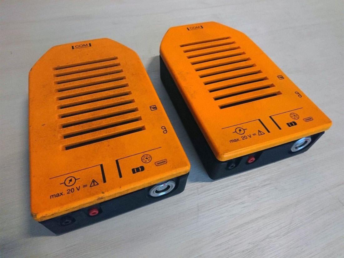
The capability for wireless connection in BMW computer diagnostics appeared in the original MoDiC 3 tester, when the diagnostic interface (the orange head) was separated from the diagnostic computer (the MoDiC 3 tablet). From that point on, all subsequent versions of DIS gained software-level support for wireless communication.
The orange diagnostic head and the MoDiC 3 tablet, manufactured by Kontron, are equipped with PCMCIA Wi-Fi cards — Netwave AirSurfer Wireless, compliant with the IEEE 802.11 2.4GHz standard. The SCO OpenServer operating system and the BMW DIS diagnostic software lack universal software and hardware compatibility. Therefore, activating wireless communication in DIS is only possible between two identical AirSurfer Wi-Fi cards and only between the orange head and the MoDiC 3 tablet. Any attempts to connect the head via radio link to another MoDiC or computer are doomed to failure.
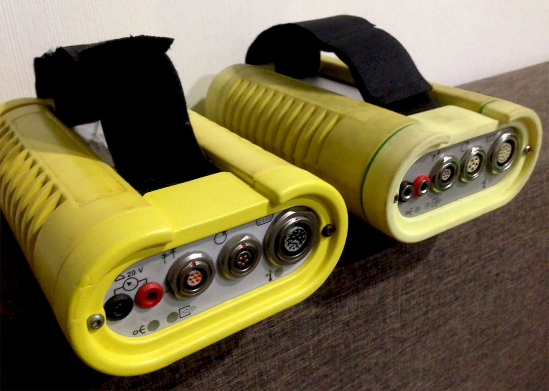
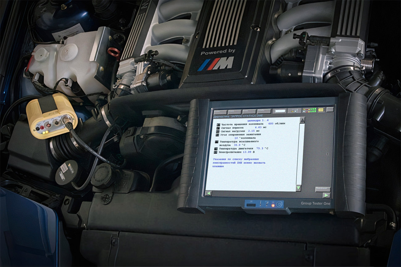
MoDiC 3 was succeeded by the BMW DISPlus and Group Tester One (GT1/MoDiC 4) diagnostic units, and with them came a new diagnostic interface — the BMW EDIC (the yellow head).
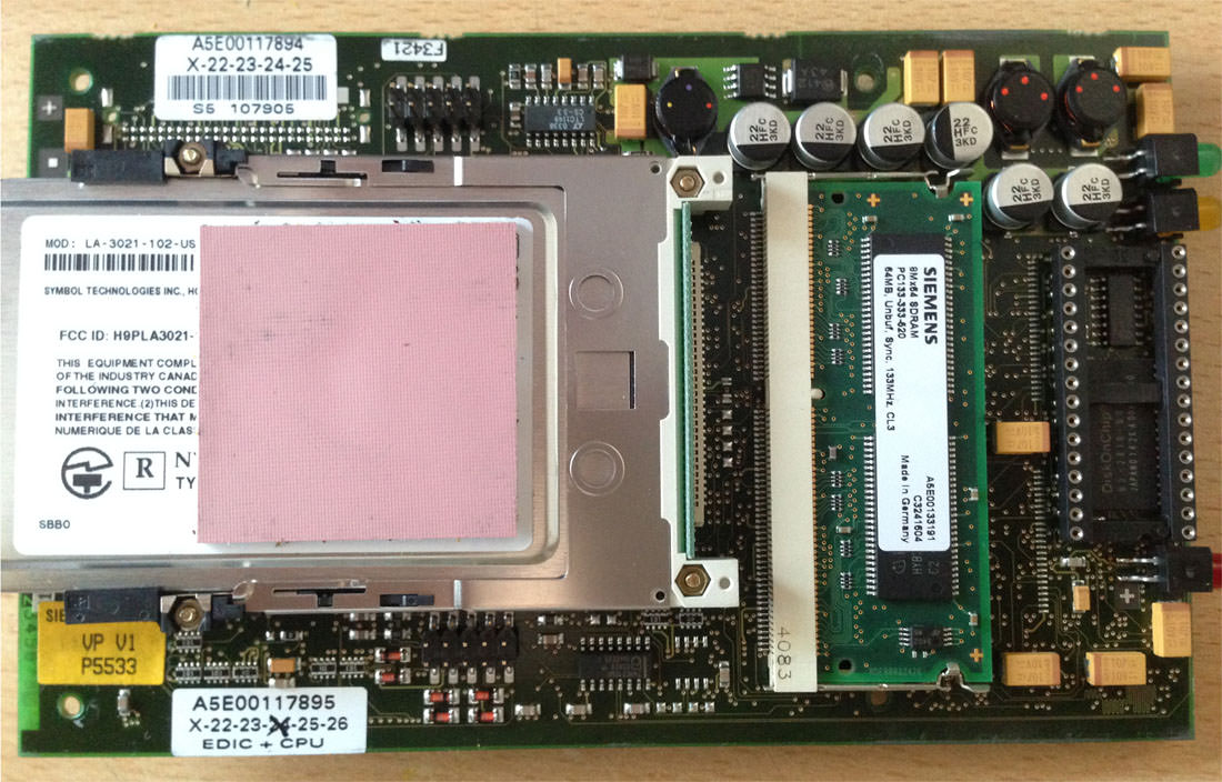
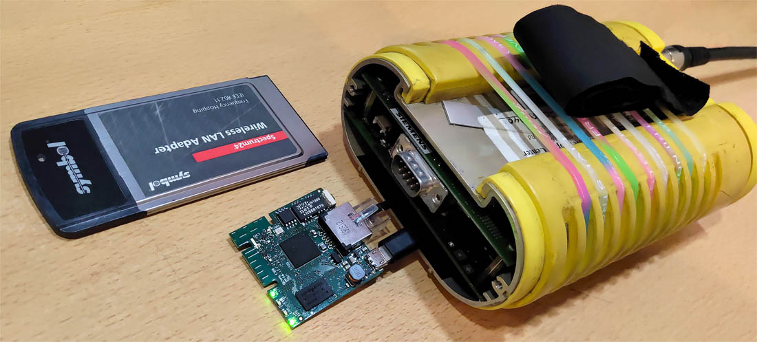
All three of these diagnostic units feature PCMCIA Wi-Fi cards — Symbol Technology Spectrum24 LA3021, compliant with the IEEE 802.11 2.4GHz standard. Just as with the MoDiC 3, activating wireless communication in DIS is only possible between these three specific units. All drivers and settings within DIS are rigidly tied to the specific components of the original diagnostic hardware.
In theory, installing the same Wi-Fi card into an IBM T30 laptop and performing a native DIS installation would enable radio communication between the laptop and the yellow head. However, I have never encountered any practical implementations of this.
There is nothing magical about the IBM Thinkpad T30. Some claim DIS works on the T30 because it has nearly the same motherboard as the BMW Group Tester One. But that is absolutely incorrect.
IBM T30 — has a typical motherboard for IBM laptops of that era.
Group Tester One — has a specialized motherboard for industrial PCs manufactured by Fujitsu-Siemens.
DIS can be installed on any computer whose hardware closely resembles the internal components of the Group Tester One tablet, specifically in terms of processor generation, chipset, and general hardware layout.
Conclusion — any attempts to use the native radio communication function to connect the diagnostic head to DIS running on a VMware virtual machine are doomed to fail. Without the MoDiC 3, GT1 tablets, or the stationary DISPlus, you can forget about using the factory Wi-Fi connection.
But it's no great loss. IEEE 802.11 — is the very first Wi-Fi standard, introduced in 1997. It has only two data transfer rates: 1 and 2 Mbps, and completely lacks backward compatibility with subsequent standards like 802.11a/b/g/n/ac. It's enough to lose line-of-sight between the tablet and the head, or move just 5 meters away, and DIS will lose the connection.
So what to do?
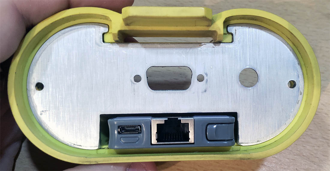
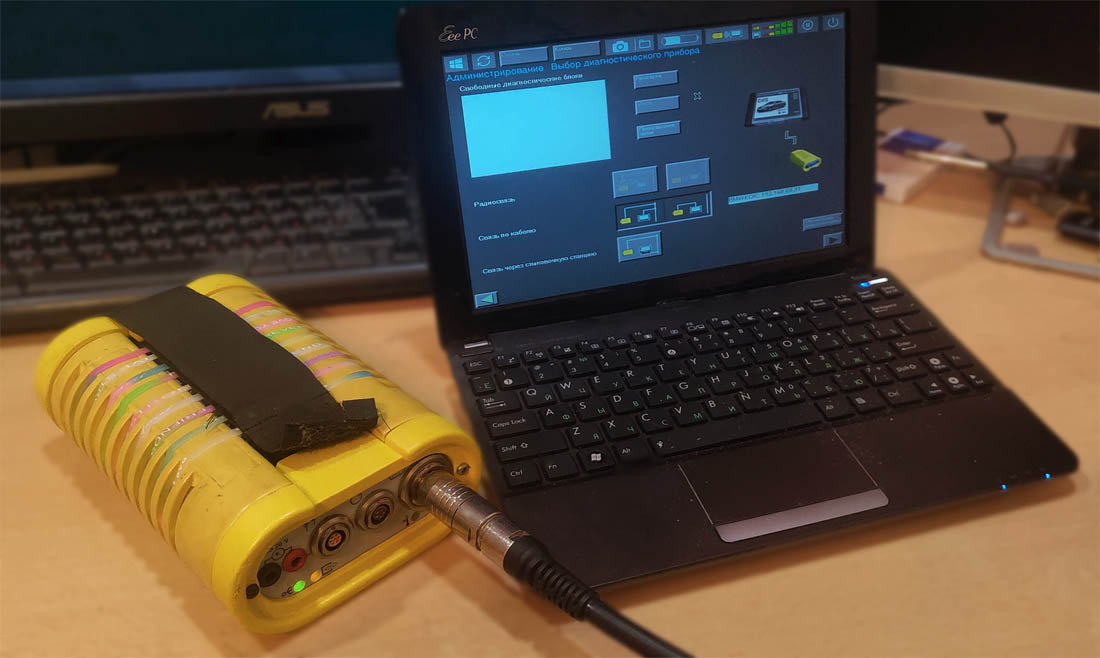
The key difference for us between the diagnostic interfaces (heads) of the MoDiC 3 and Group Tester One is that the orange head (MoDiC 3) uses the RS-232 standard (COM port) for wired connection, while the yellow head (GT1) uses the Ethernet standard. A familiar network cable. Which has much greater backward compatibility. And that's what we'll use.
DIS has multiple ways to communicate with the yellow head, but we are only interested in the direct connection method via network cable. Because this is the only possible way to connect the yellow head to DIS installed on a VMware virtual machine.
Our task is to connect the yellow head to the computer via Wi-Fi, while simultaneously forcing DIS to believe we are using a network cable.
It's sufficient to attach a Wi-Fi router to the end of the network cable and transmit data packets through the air. And thanks to the universality and backward compatibility of Ethernet, we can use the most modern Wi-Fi standards like 802.11n/ac. This will provide a reliable wireless connection even over tens of meters between the yellow head (GT1) and the computer running DIS on a VMware virtual machine. DIS won't even know about the additional node in the network and will think we're still just using a network cable.
Data packets can even be transmitted over the internet, allowing the diagnostic EDIC interface and the DIS computer to be thousands of kilometers apart. The main thing is not to exceed the TTL.
Actually, the COM port can also be made wireless by using two Wi-Fi or Bluetooth converters in between. Scheme: orange head <—> converter <—> air <—> converter <—> laptop with DIS. But even connecting the orange head via a wired COM connection to DIS on a VMware virtual machine is a nearly unsolvable task, let alone attempts to create a wireless one. The MoDiC 3 is not the most successful unit.
And how do we do this?
We buy any miniature Wi-Fi router, for example: TP-Link TL-WR702N, TP-Link TL-MR3020, Mikrotik mAP lite. There's no need to buy a large home router; we are, after all, creating a compact solution. The router operates on 5 volts. Therefore, we'll need any miniature 12V to 5V power converter, with high-capacity capacitors. During engine start, the starter draws high current, causing interference, noise, and voltage spikes in the vehicle's electrical system. Without a high-quality power converter, the router will constantly glitch, reboot, or even burn out.
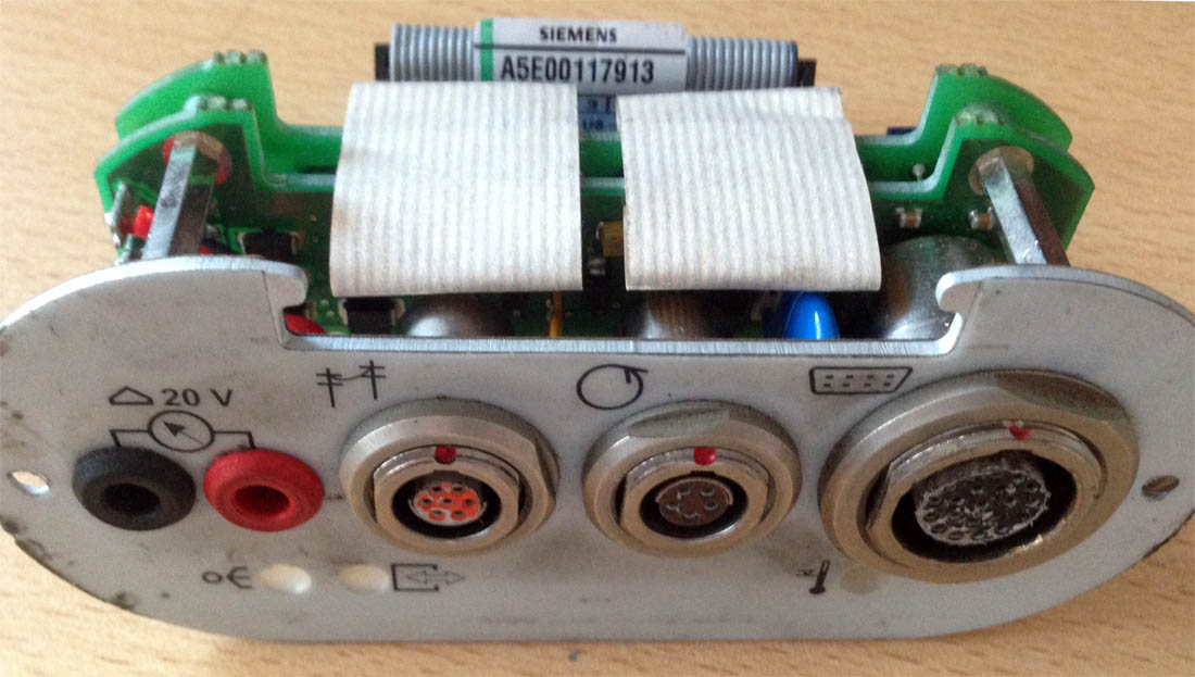
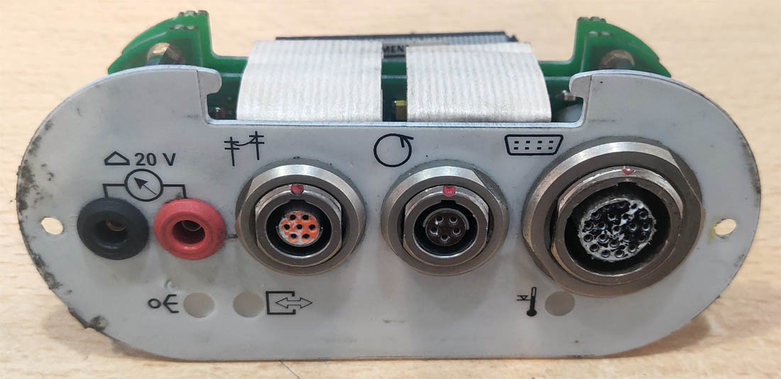
To supply 12 volts to the power converter, we can utilize the unused measurement connectors on the front of the yellow head. But this requires disassembling the EDIC and resoldering wires to apply 12 volts from the vehicle's electrical system to those measurement connectors.
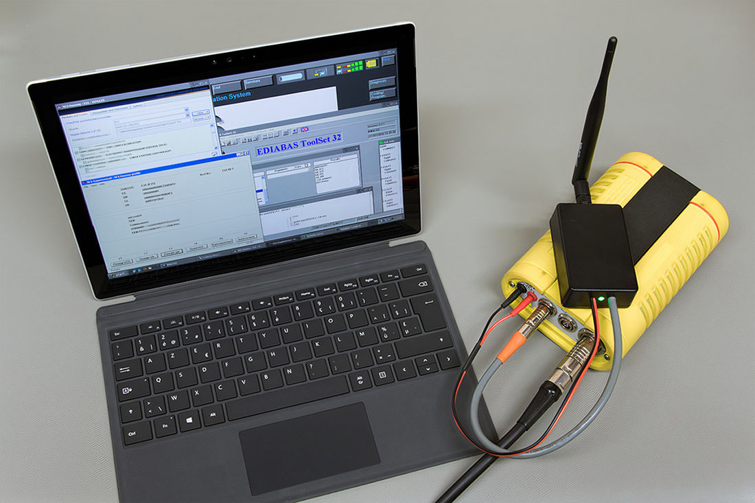
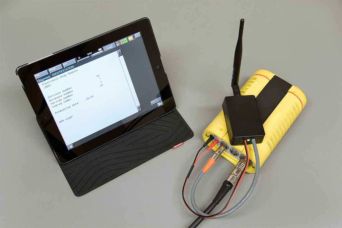
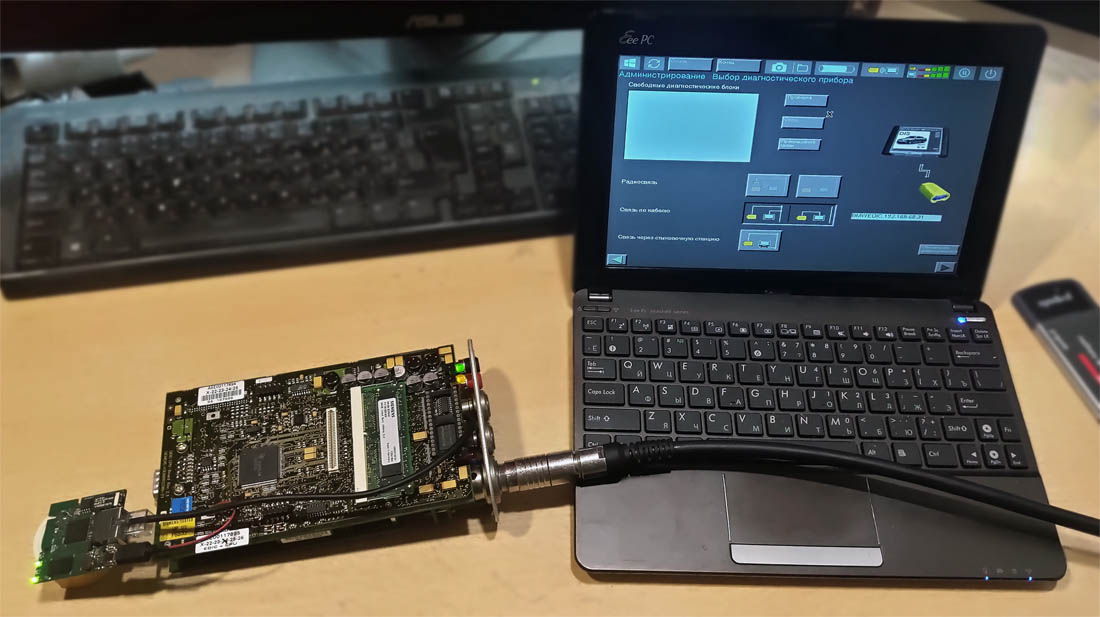
We connect: the power converter to the router, the network cable from the diagnostic head to the router. We configure the router and connect from the computer to the Wi-Fi access point. In the end, we achieve a wireless connection between the EDIC and DIS.
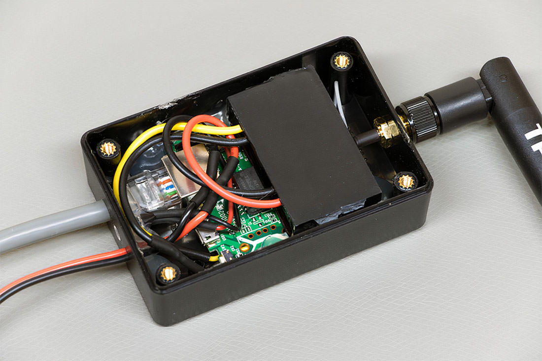
This implementation requires minimal intervention into the diagnostic head, but the router and power converter will be located outside the head. For convenience, all components of the Wi-Fi access point were packaged into a single box.
How to get rid of the external box?
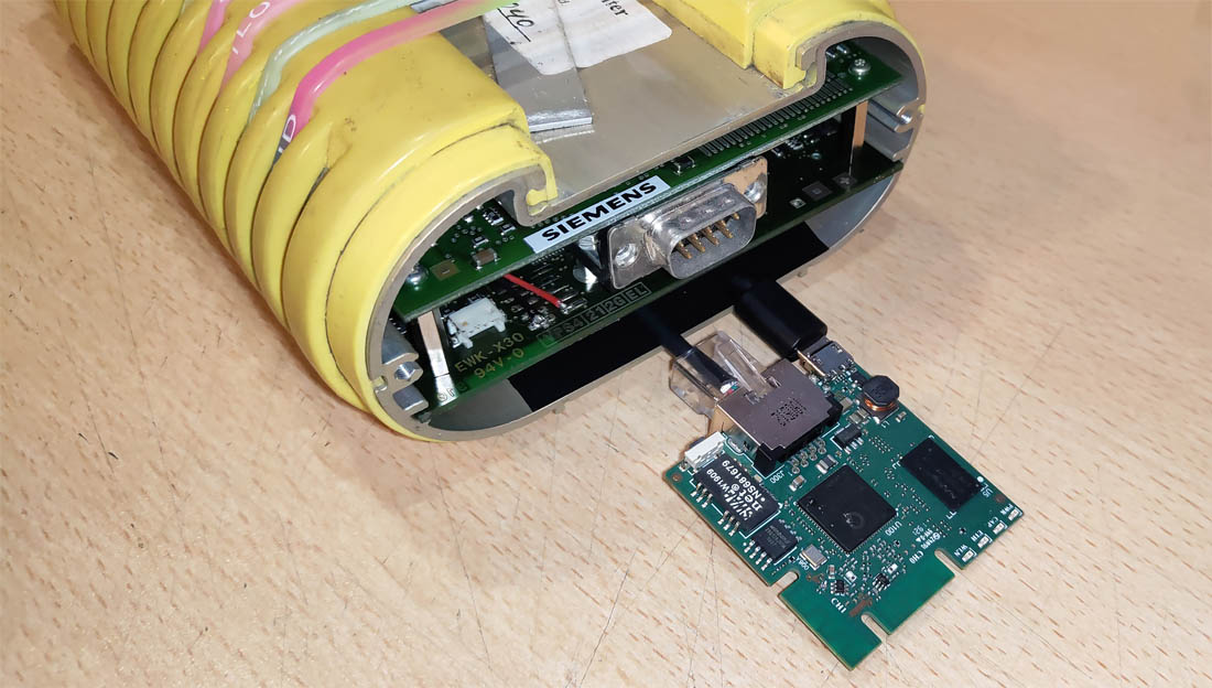
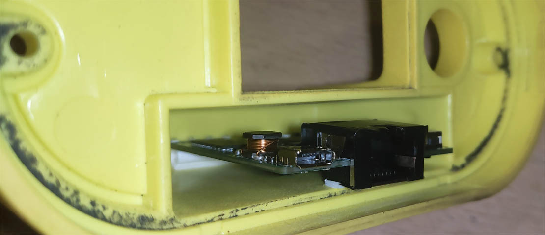
All components can be placed inside the diagnostic head, exactly as done in the original EDIC. This requires significantly more intervention into the head, but the result will be the complete absence of external Wi-Fi access point components. I will describe the process of installing the router inside the original yellow Siemens EDIC diagnostic head and its Chinese clone.
Original EDIC Diagnostic Head
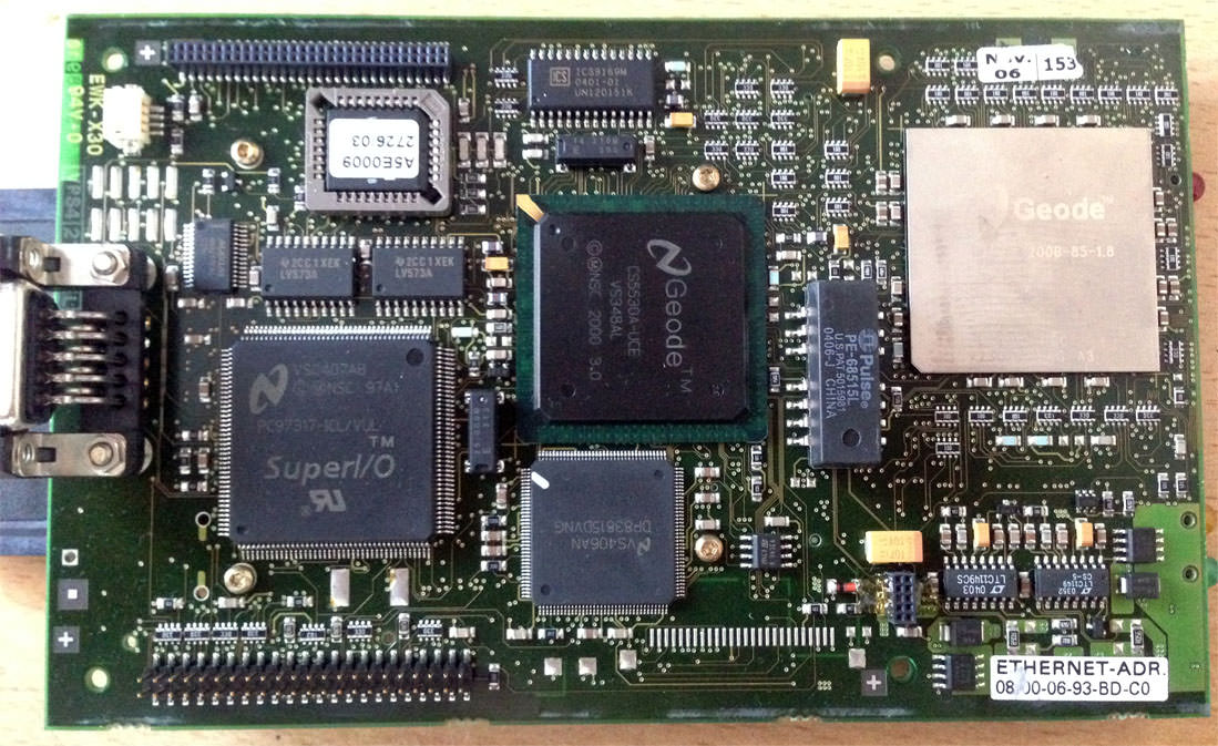
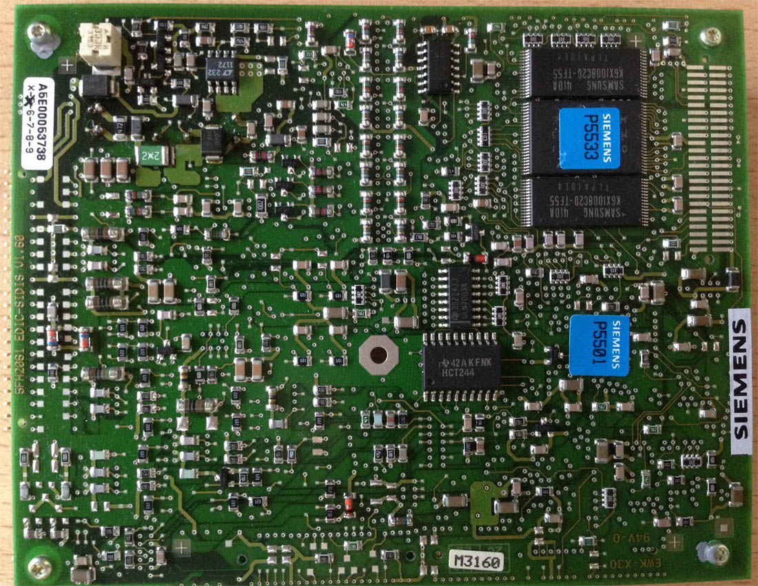
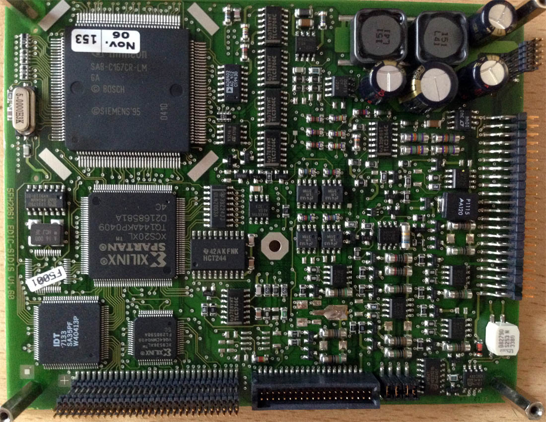
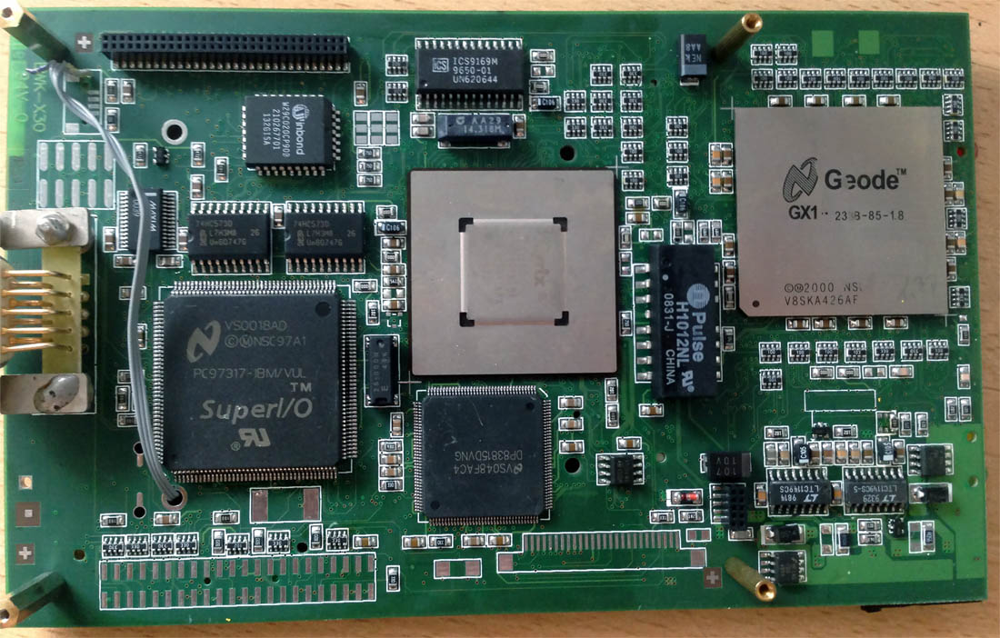
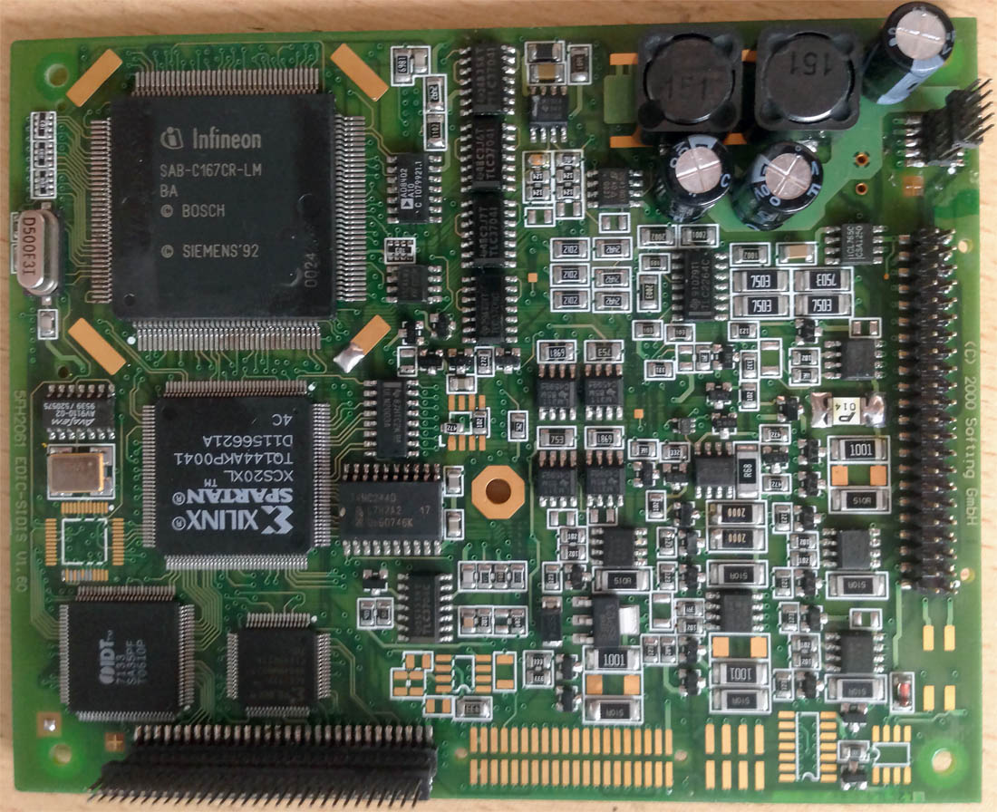
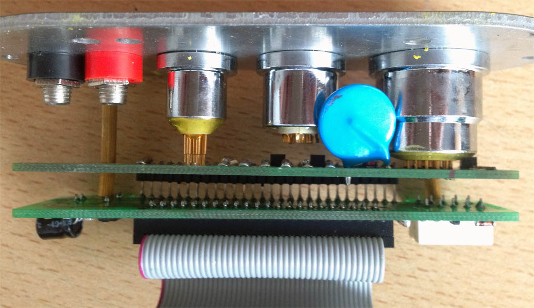
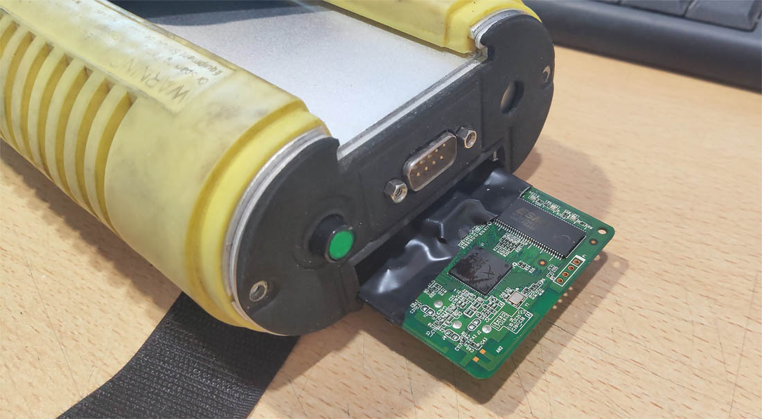
We completely disassemble the casing of the yellow head and separate the three internal boards from each other.
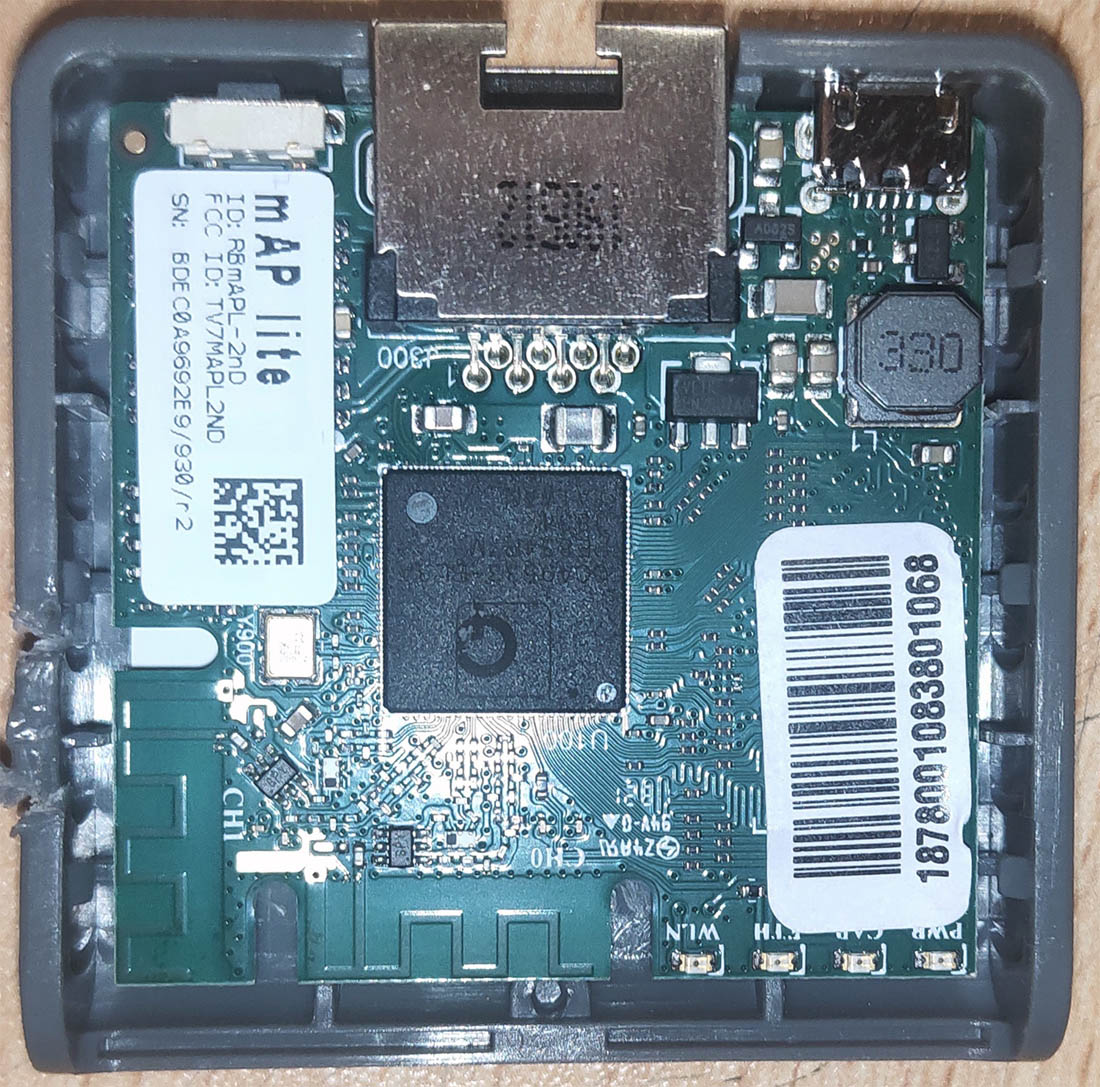
For the Wi-Fi access point, I purchased a Mikrotik mAP lite. This is an incredibly small router, probably the smallest available on the market. Even without disassembling its casing, it can fit inside the head's casing.
Unfortunately, when assembling the head's casing with the router inside, it will still interfere with some elements on the EDIC's computer board. It's short by just half a centimeter.
The router still fits, but barely. You could leave it like that, but then during assembly, you might damage components on the board. Alternatively, you can disassemble the router's casing and extract the board to gain that crucial half a centimeter. That's what we'll do.
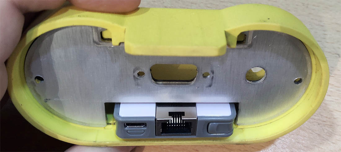
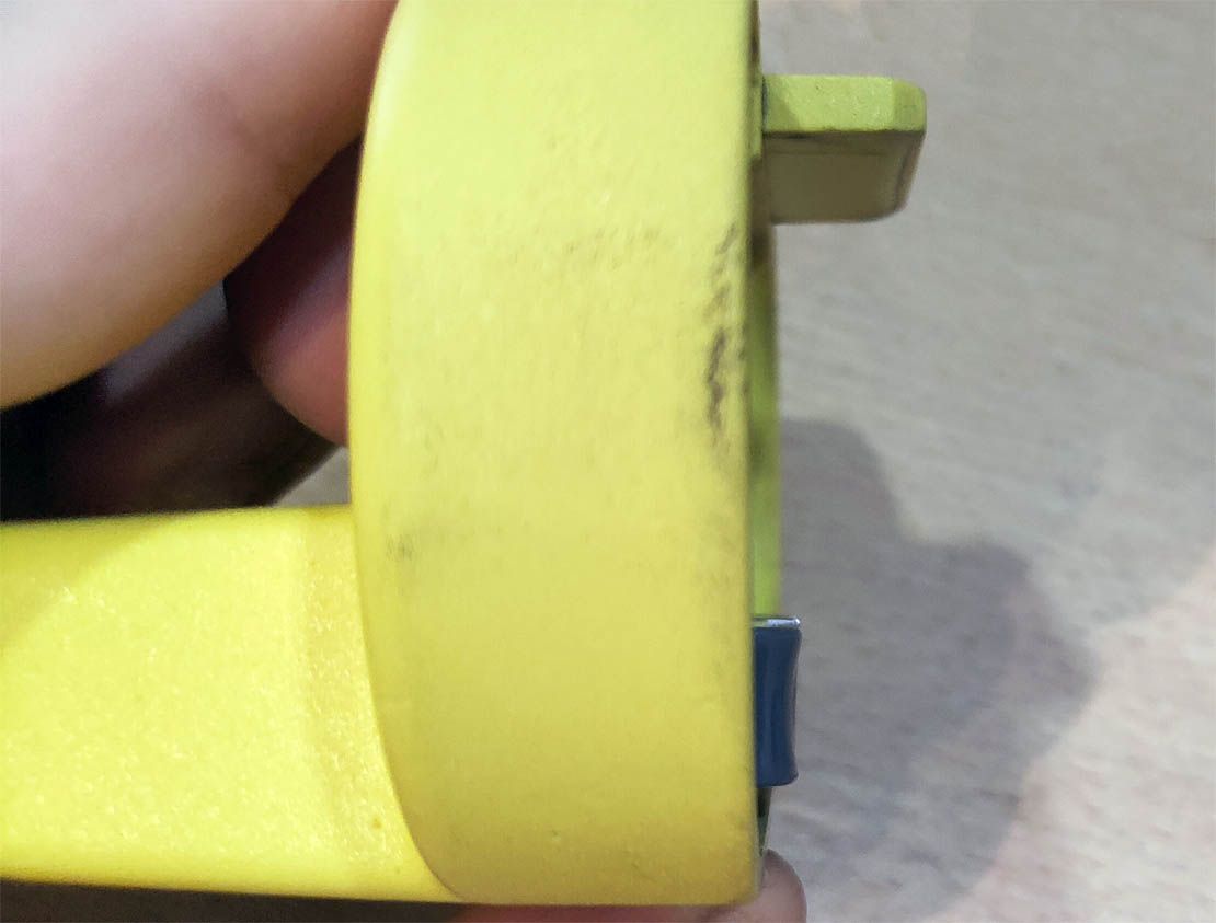
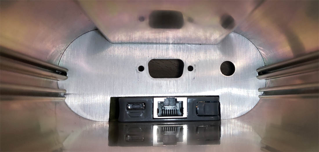
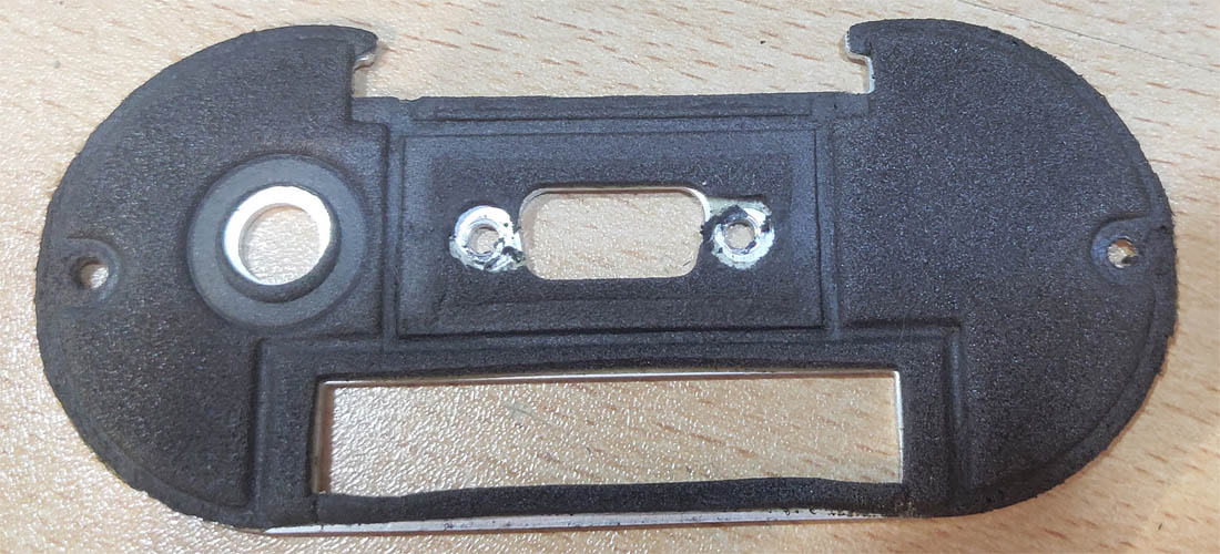
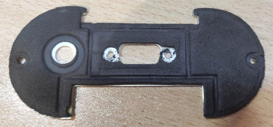
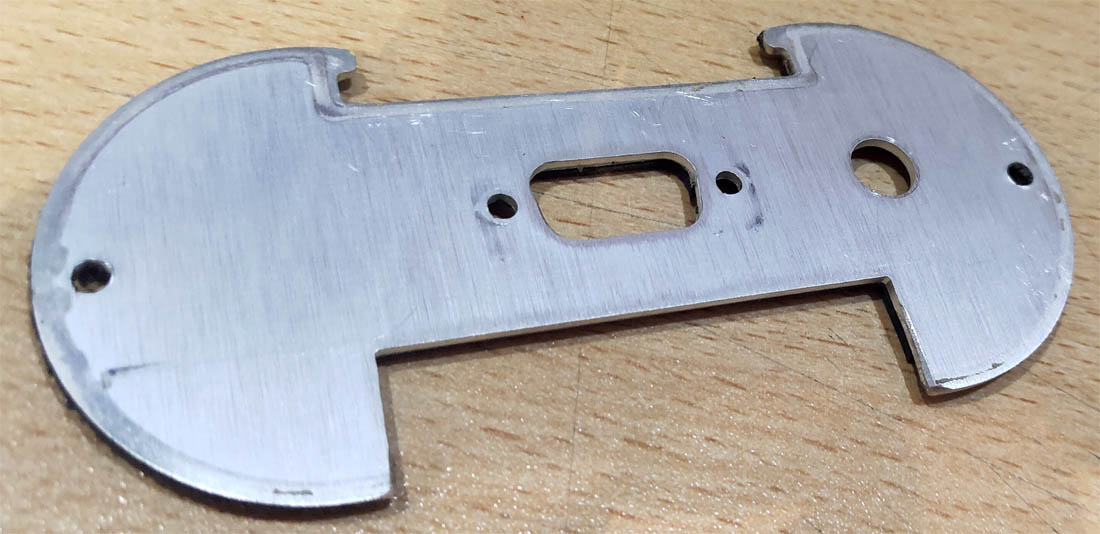
We remove the aluminum partition from the head's casing sled to lower the router's board a couple of millimeters.
The router operates on 5 volts. When placing the router outside the head, the size of the 12V to 5V power converter isn't a problem. Inside the head's casing, we are severely limited in free space and cannot fit a powerful power converter. Providing stable power to the router is the main task of this entire head modification. Without this, achieving a quality wireless connection is impossible. We would face constant glitches, connection drops, and router reboots at the slightest hiccup in the vehicle's voltage. The market lacks high-quality miniature power converters. Everything is produced in China, and in any case, the converter will need to be manually refined with a file.
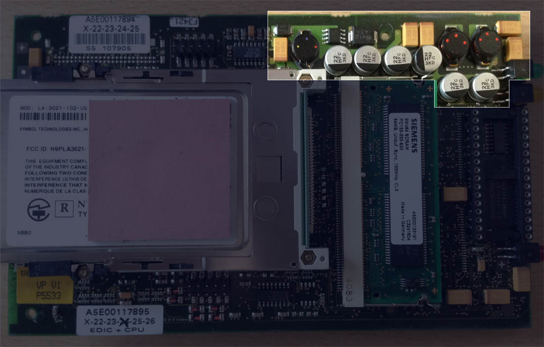
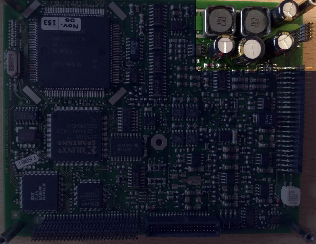
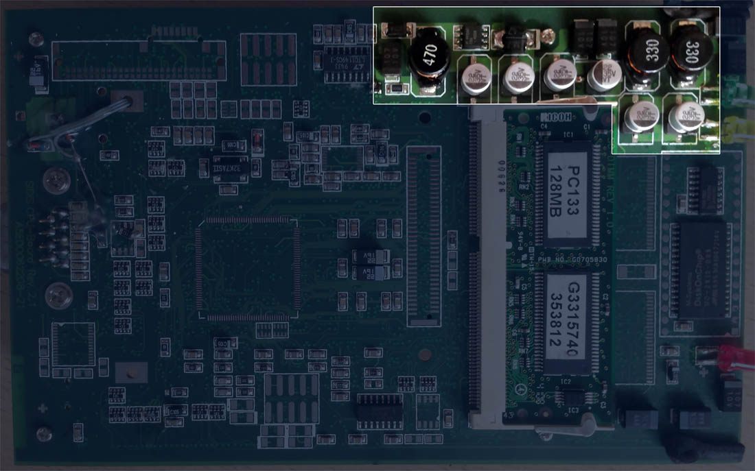
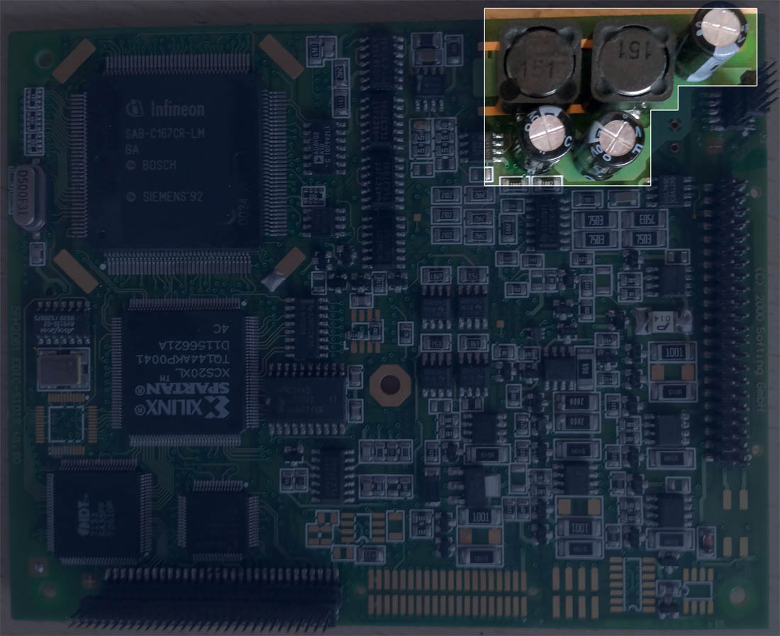
The diagnostic head has two very powerful and high-quality power supply units. Exactly the same kind used in all desktop computers. Except that a computer PSU converts 220V AC into three DC power rails: 3V, 5V, and 12V. While the head's power supplies convert the constant 12V from the vehicle's electrical system into constant 3V and 5V DC rails.
Actually, three boards of the yellow head work simultaneously in voltage conversion, power stabilization, short-circuit, and reverse polarity protection, not each one separately.
We can easily connect additional consumers to the output rails of a computer PSU: hard drives, disk drives, coolers, LED strips. The motherboard, processor, or graphics card won't perform worse because of it. Power supplies are made precisely for that — to power consumers. As long as there's enough capacity.
The diagnostic head is essentially a computer itself. Therefore, we can also connect our own current consumers to the power supply rails of the diagnostic head. And the head won't perform worse because of it. The head's power supplies are designed with a power reserve. The main task is to take power precisely from the 5V output rail of the power supply, and not from, for example, the processor or RAM power circuit. Or a power circuit controlled by the processor. For instance, the power to the integrated Wi-Fi card is managed by the processor. And if the card is not in use, the processor turns it off.
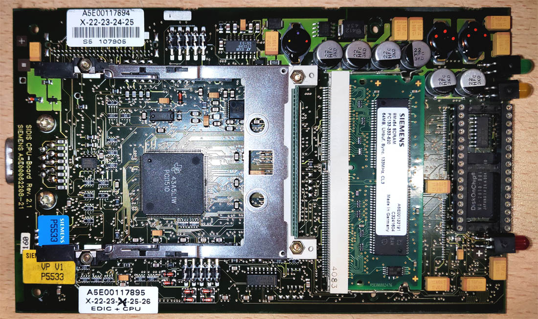
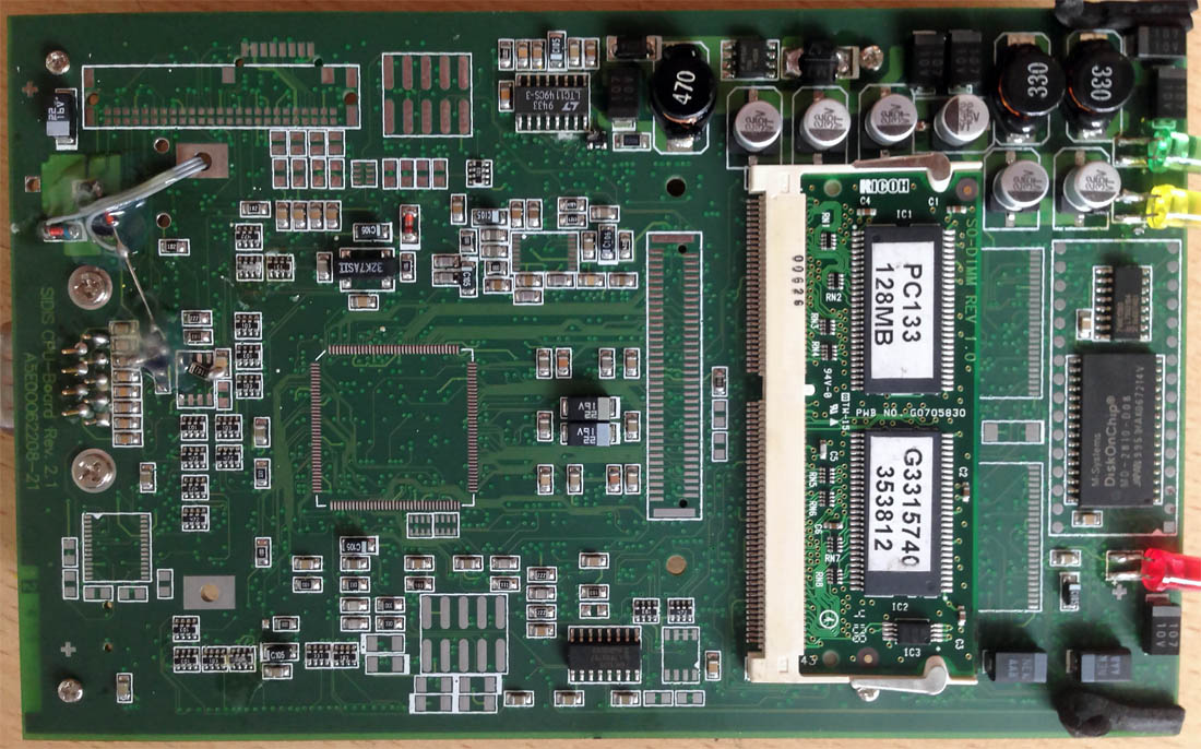
We begin to free up space for our router. The original Wi-Fi card is located on the computer board of the yellow head. We disconnect it. The head and wired connection work without it, and when a network cable is connected, the processor doesn't even supply power to the Wi-Fi card.
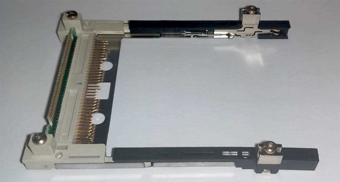
We unscrew and remove the Wi-Fi card mounting plate.
Where to get power?
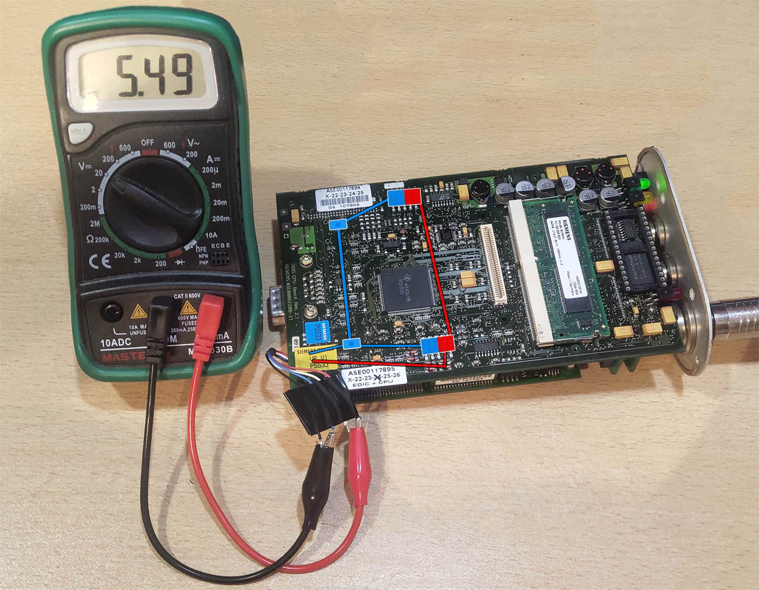
By removing the native Wi-Fi card, we have freed the computer board's power supply from an extra consumer. It's logical to use this and power our router from this very board. In this case, we can be confident the power supply won't be overloaded. The EDIC's Wi-Fi card and our router consume approximately the same amount of current — 250mA.
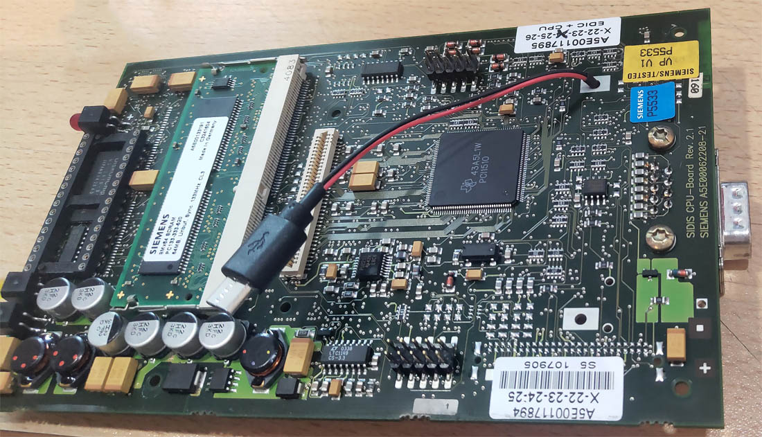
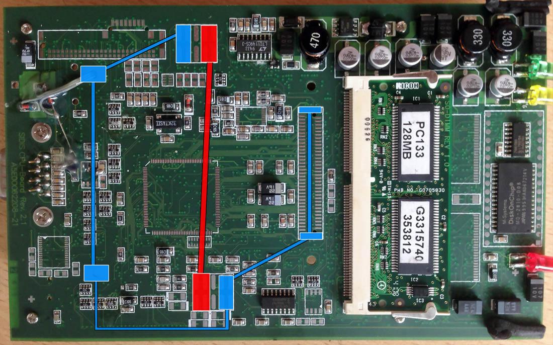
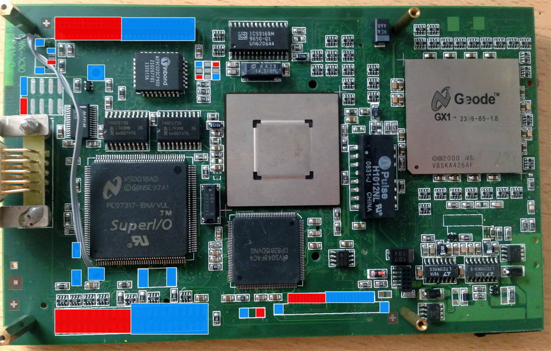
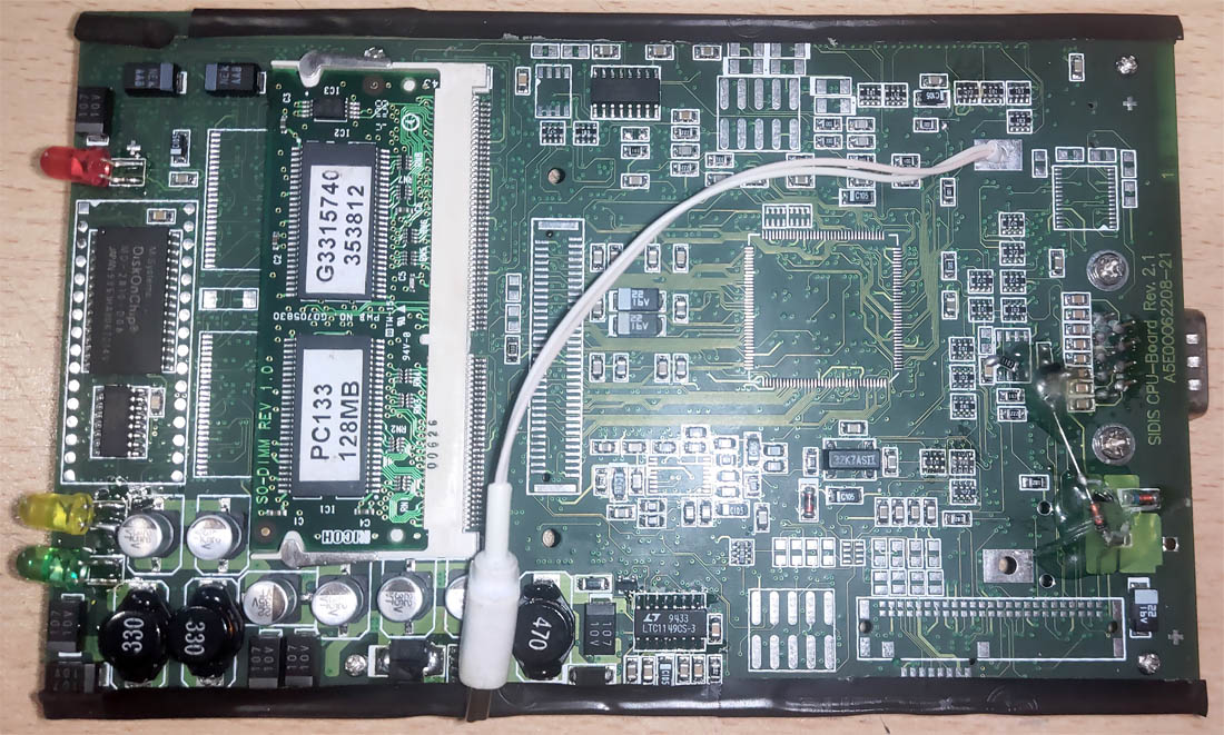
The 5V rail is available on many unused contacts designed for connecting various additional modules to the board. For example, the rail goes to the rear button of the yellow head.
The choice of connection point to the power rail will depend solely on your experience and soldering quality. I decided to use the unused contacts to the right of the button connector and routed the router's power wires to the back side of the EDIC's computer board.
Is that all?
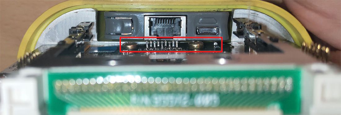
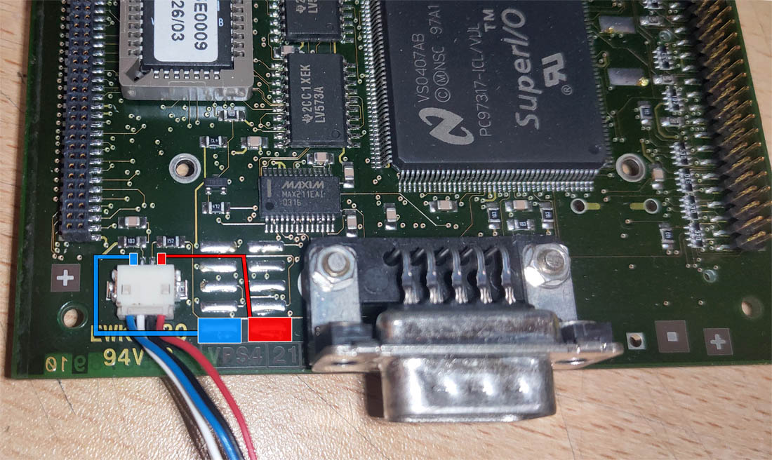
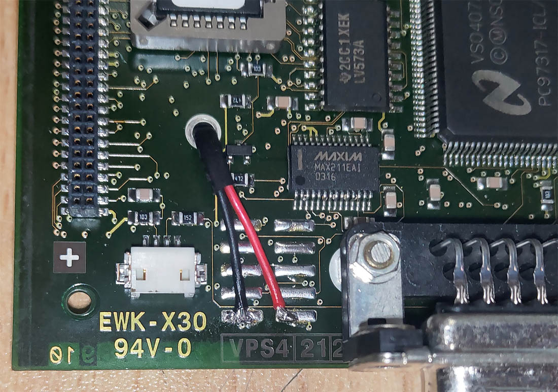
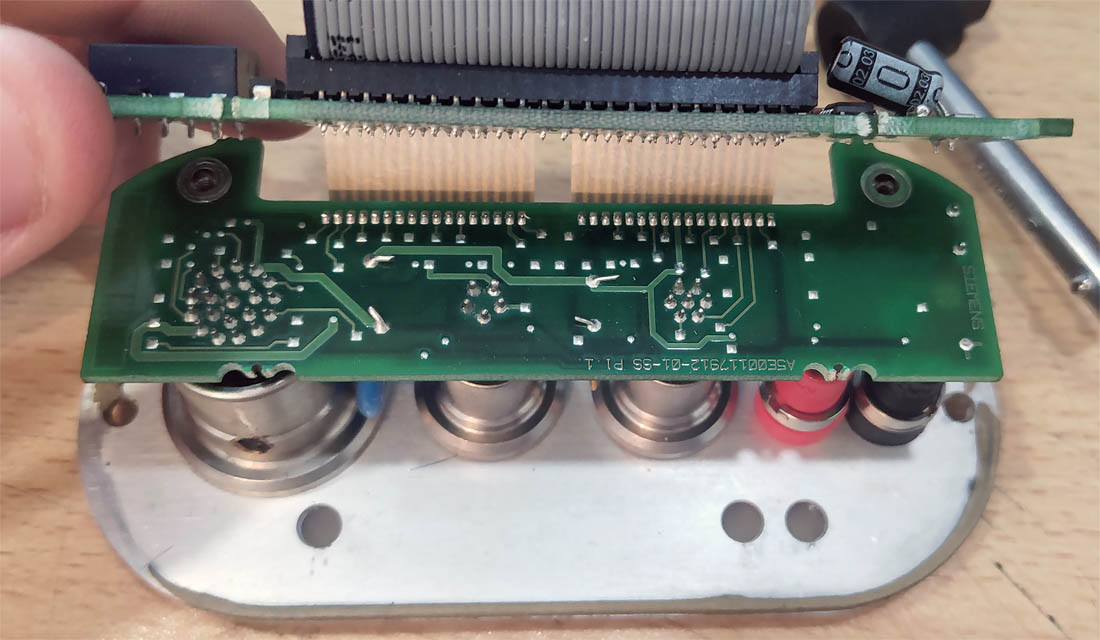
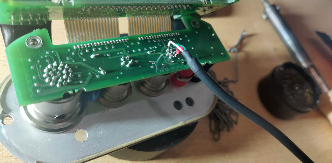
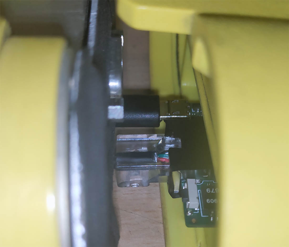
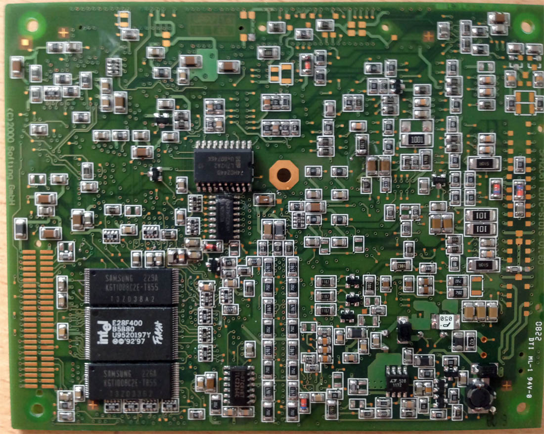
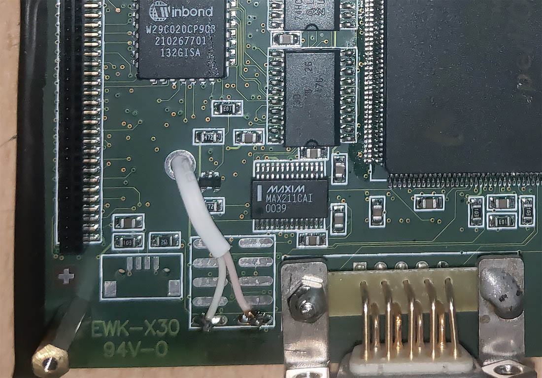
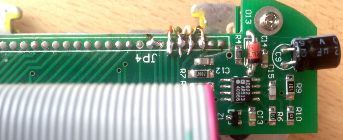
No. Now we need to take Ethernet from the head for the router. To preserve the ability to connect the diagnostic head to DIS via a wired connection, we must tap into the Ethernet from one of the head's boards. Just as with the power rail, the connection point will depend on your experience and soldering quality. I chose the front EDIC board with external connectors. It's necessary to fully simulate the use of a network cable. Connect to the 4 signal contacts and create a jumper between two contacts, thanks to which the head's computer detects that a network cable is plugged into the port.
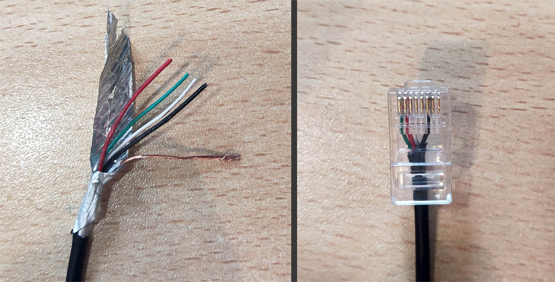
We crimp the connector for our internal network cable.
Well, is that all now?
Yes, those are all the necessary modifications to the diagnostic interface. You can connect, configure the router, and test the modification.
We secure the router in the casing sled. You can use snot, gum, Velcro, magnets, double-sided tape, squeeze it between two pieces of foam. Use your imagination.
We connect power and Ethernet to the router and assemble the head's casing. The modification of the original GT1 diagnostic head is fully complete.
Chinese Clone Diagnostic Head
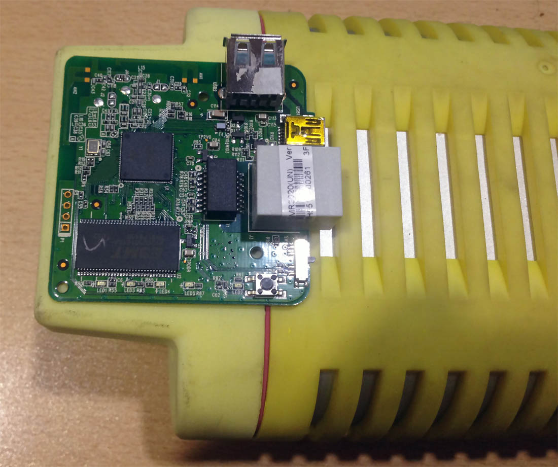
The process isn't much different from modifying the original head. We disassemble the clone EDIC casing and separate the three internal boards from each other.
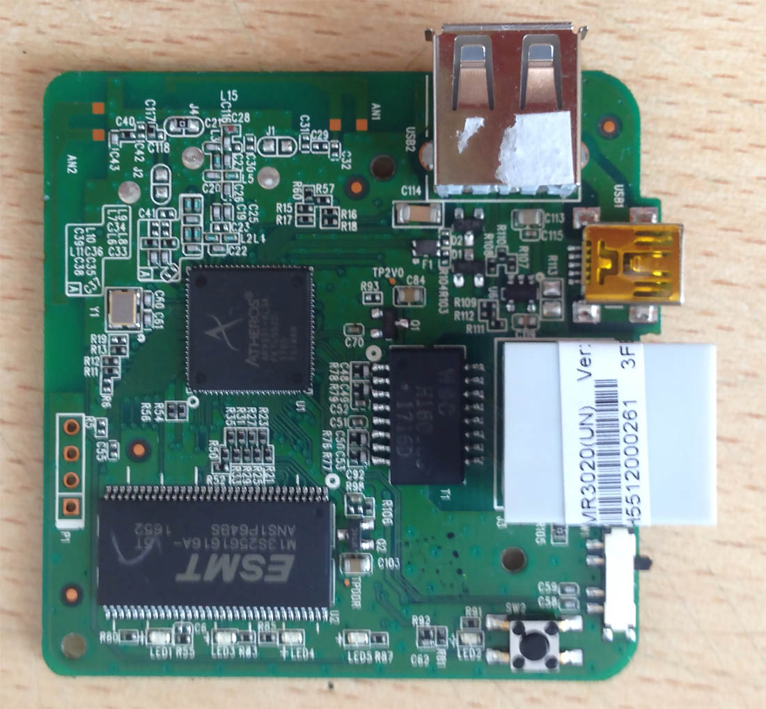
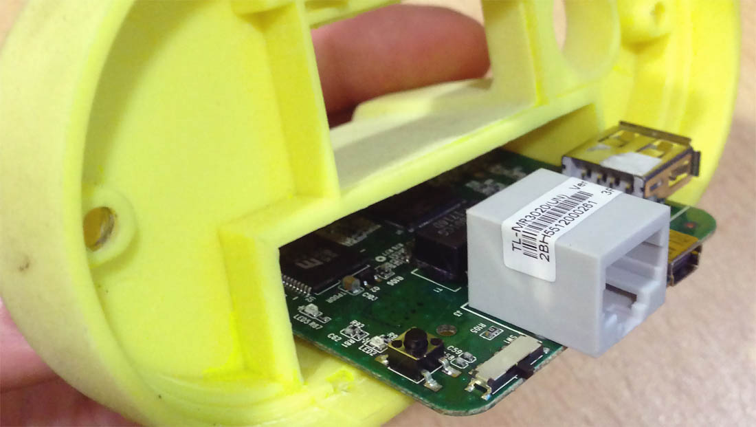
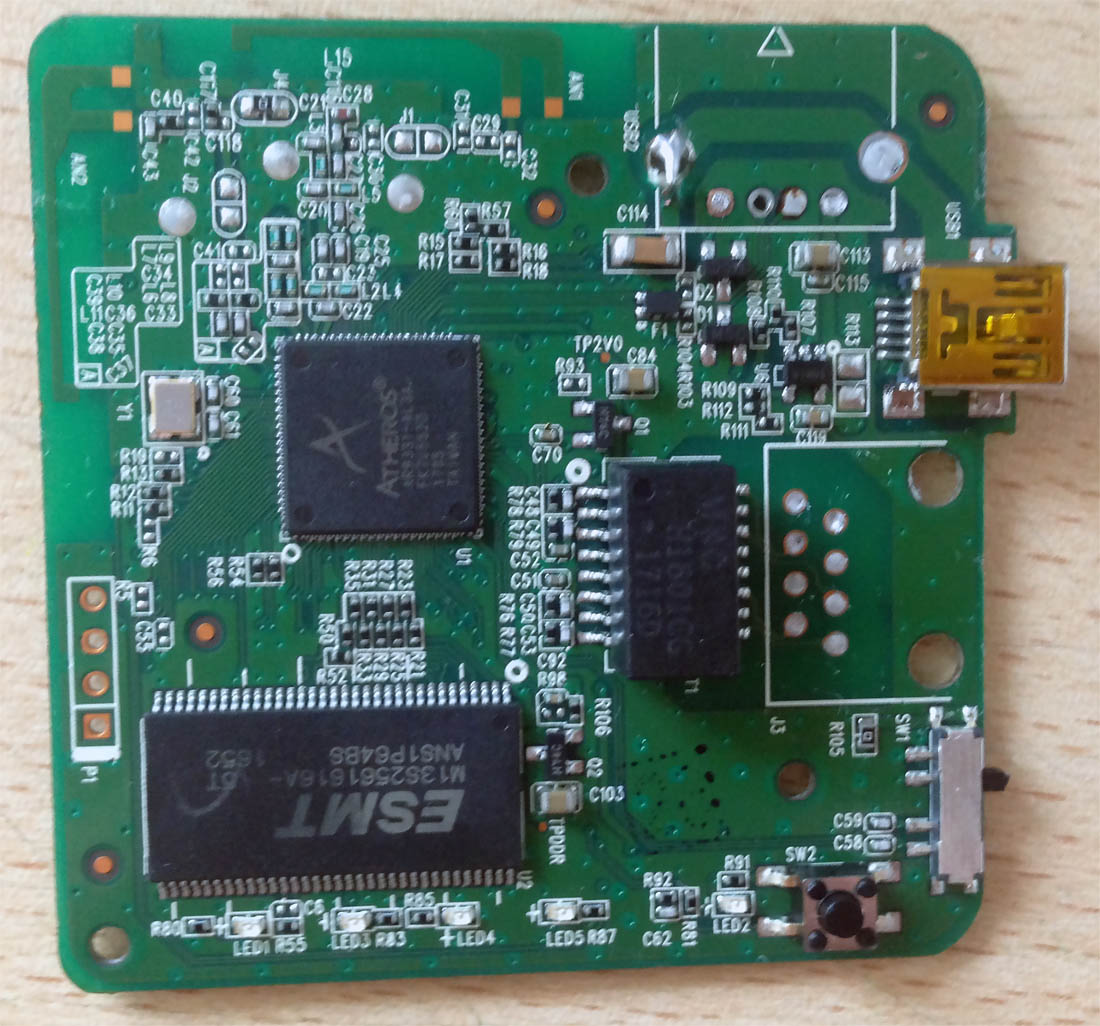
The quality of components and assembly in the Chinese yellow head is an order of magnitude lower than the Siemens original. For the Wi-Fi access point, I purchased a TP-Link TL-MR3020. The router's dimensions are much larger than the Mikrotik mAP lite, so we disassemble its casing immediately.
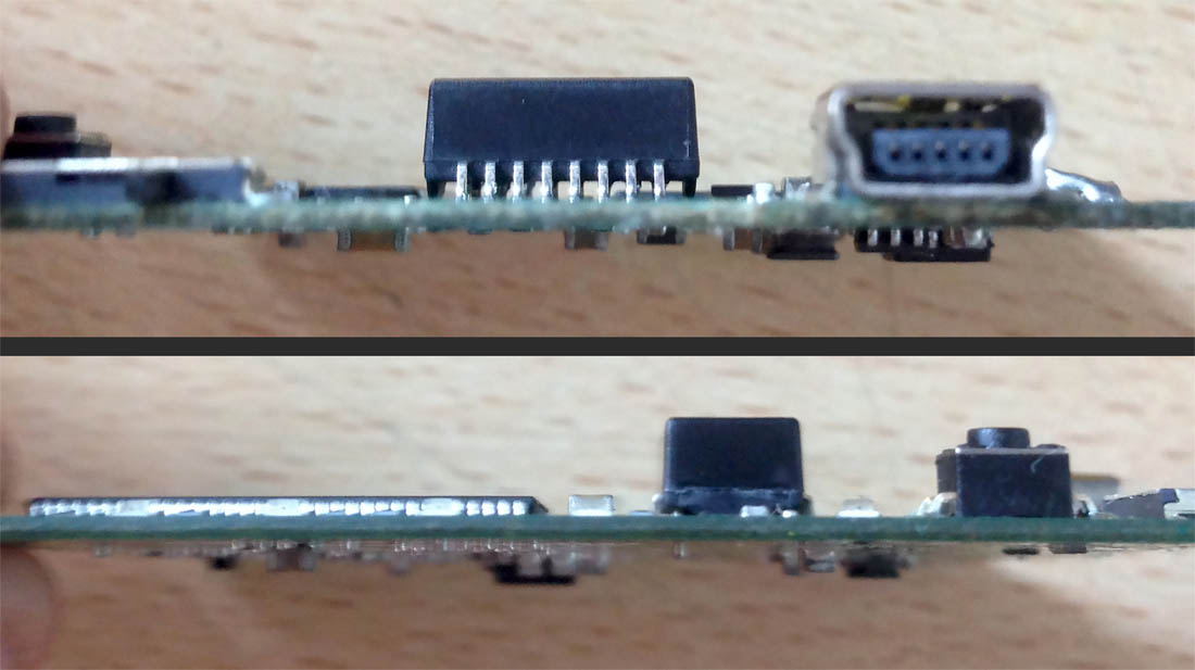
We desolder the Ethernet and USB Type A connectors from the router's board. It won't fit inside the head's casing otherwise. We solder the Ethernet signal wires directly to the contacts on the board. We leave the Mini USB for powering the router.
We remove the aluminum partition from the casing sled to free up even more space.
The power supplies on the two boards of the Chinese head are similar in capacity to the original.
Since the computer board of the Chinese clone lacks the Wi-Fi card, many components, and consumers present in the original head, it makes sense to connect to the 5V rail from its power supply. Moreover, there are more potential connection points on this board.
As with the original head, I utilized the unused contacts to the right of the button connector and routed the router's power wires to the back side of the GT1 computer board.
I simulated the network cable similarly on the front board of the diagnostic head with external connectors. But I performed the soldering at a different location.
We connect, configure the router, and assemble the head's casing. The modification of the Chinese clone is fully complete.
I didn't understand a thing 🤪
Then send the head to me by mail, and I will send it back to you ready and configured in a week. Or buy one already modified. Without understanding, it's easy to break, and repairing such a unit is nearly impossible. Meow.
